5 self-calibration, 3 bridge resistance measurements, Figure 28: voltage excitation bridge circuit – Campbell Scientific CR200/CR200X-series Dataloggers User Manual
Page 53
Section 4. Sensor Support
4.2.5 Self-Calibration
A calibration measurement to measure the ground offset is made at the
beginning of each measurement instruction that includes a voltage
measurement. This calibration takes about 400 microseconds. Only one
calibration measurement is made per instruction regardless of the number of
reps.
The battery voltage is checked every 8 seconds to ensure it is within the
allowable range.
4.3 Bridge Resistance Measurements
Many sensors detect phenomena by way of change in a resistive circuit.
Thermistors, strain gages, and position potentiometers are examples. Resistance
measurements are special case voltage measurements. By supplying a precise,
known voltage to a resistive circuit, then measuring the returning voltage,
resistance can be calculated.
Two bridge measurement instructions are included in the CR200(X), ExDelSE
() and Therm109 (). ExDelSE () is used with sensors that have a simple half
bridge circuit. Therm109 () is used with Campbell Scientific’s 109-L thermistor
probe. Sensors with bridge circuits that require a differential voltage
measurement, such as full bridge or 3-wire half bridge, cannot be measured with
the CR200(X).
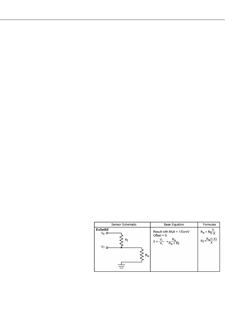
FIGURE. Half Bridge Circuit Used with ExDelSE
(p. 41) shows the circuit that
is typically measured with ExDelSE (). In the diagram. Rs is normally the
sensor and Rf is normally a precision fixed (static) resistor. Vx is the excitation
voltage (either 2500 or 5000 mV) and V1 is the voltage (mV) measured by the
analog input channel.
Calculating the resistance of a sensor that is one of the legs of a resistive bridge
requires additional processing following the bridge measurement instruction.
FIGURE. Half Bridge Circuit Used with ExDelSE
(p. 41) lists the schematics of
a typical half bridge configuration and the calculations necessary to compute the
resistance of any single resistor, provided the value of the other resistor in the
bridge circuit is known.
Figure 28: Voltage Excitation Bridge Circuit
41