Horner APG RX371 OCS HERX371C101 User Manual
Page 72
CH. 12
MAN0924-01-EN
February 8, 2010
Page 72 of 124
# 1018
12.1.3 Resource
Definitions
System Registers
System Registers (%S and %SR) are used to store general RX-371 status information. This
information is used internally, and is also available to the operator via the System Menu, using the
RX-371 display and keypad. The System Registers are also available for User Screens and can be
accessed by Ladder Code.
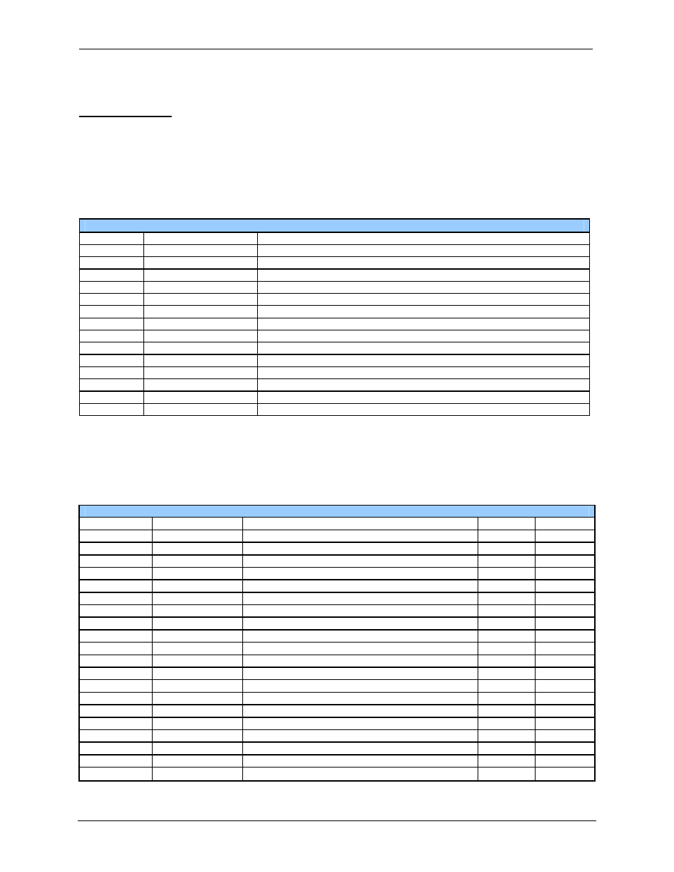
%S Registers
%S Registers are 1-bit memory locations containing system status information, which are
implemented as shown in Table 12.2:
Table 12.2- %S Registers
Register Name
Description
%S1
FST_SCN
On during the first scan after entering RUN mode
%S2
NET_OK
On if CsCAN Network is functioning properly
%S3
T_10MS
On for 5 mS; Off for 5 mS
%S4
T_100MS
On for 50 mS; Off for 50 mS
%S5
T_SEC
On for 500 mS; Off for 500 mS
%S6
IO_OK
On if SmartStack I/O is configured properly
%S7
ALW_ON Always
On
%S8
ALW_OFF Always
Off
%S9
PAUSING_SCN
On during the last scan before Pause-N-Load
%S10
RESUMED_SCN
On during the first scan before Pause-N-Load
%S11
IO_FORCED
On if one or more I/O points are currently being forced
%S12
IO_FORCING
On if I/O forcing is enabled
%S13
NET_IO_OK
On if Network I/O (SmartStix) is functioning properly
%S16
Ethernet COM module is OK
%SR Registers
%SR Registers are 16-bit memory locations, containing system status information, implemented as
shown in Table 12.3.
Note: Where 2 %SRs are combined to make a 32-bit value, the lower numbered %SR is the low word,
while the higher numbered %SR is the high word.
Table 12.3- %SR Registers
Register
Name
Description
Min Val
Max Val
%SR1
USER_SCR
Current User Screen Number
1
1023
%SR2
ALRM_SCR
Current Alarm Screen Number (0=none)
0
1023
%SR3
SYS_SCR
Current System Screen Number (0=none)
0
14
%SR4
SELF_TEST
Bit-Mapped Self-Test Result
0
65535
%SR5
CS_MODE
Control Station Mode (0=Idle, 1=Do I/O, 2=Run)
0
2
%SR6
SCAN_RATE
Average Scan Rate ( / 10)
-
1000
%SR7
MIN_RATE
Minimum Scan Rate ( / 10)
-
1000
%SR8
MAX_RATE
Maximum Scan Rate ( / 10)
-
1000
%SR9-10
EDIT_BUF
Data Field Edit Buffer
0
2
32
-1
%SR11-12
LADDER_SIZE
Ladder Code Size
2
256K
%SR 13-16
Reserved -
-
-
%SR17-18
IO_SIZE
I/O Configuration Table Size
16
127K
%SR19-20
NET_SIZE
Network Configuration Table Size
34
1K
%SR21-22
SD_SIZE
Security Data Table Size
-
-
%SR23
LADDER_CRC
Ladder Code CRC
0
65535
%SR 24-25
Reserved -
-
-
%SR26
IO_CRC I/O
Configuration Table CRC
0
65535
%SR27
NET_CRC
Network Configuration Table CRC
0
65535
%SR28
SD_CRC
Security Data Table CRC
0
65535
%SR29
NET_ID
This Station’s Primary Network ID (CsCAN)
1
253