Red Lion GEMINI 52 User Manual
Page 39
SENSOR INPUT CONNECTIONS & INPUT CONFIGURATION
SWITCH SET-UP
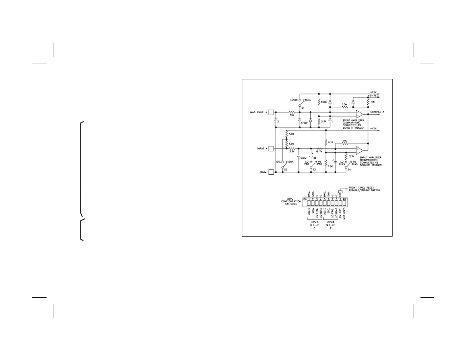
The accompanying diagram shows the details of the logic and magnetic
pickup circuitry. The four switches used to set up Logic Input A and Magnetic
Pickup A are designated S1, S2, S3, and S4. The four switches used to set up
Logic Input B and Magnetic Pickup B are designated S5, S6, S7, and S8. The
functions of these switches are as follows:
S1 - MAG: Enables the Magnetic Pickup terminal to be used.
LOGIC: Disables the Magnetic Pickup Input.
Note: SWITCH S2 MUST BE IN THE “SNK” POSITION FOR
MAGNETIC PICKUP OPERATION.
S2 - SNK: Provides a 7.8 K pull-up resistor for sensors with current sinking
outputs.
SRC: Provides a 3.9 K pull-down resistor for sensors with current
sourcing outputs.
S3 - HI FRQ: Removes damping capacitor and allows operation up to the
max. count frequency. Min. count ON or OFF time - 50 usec.
LO FRQ: Connects damping capacitor for switch contact debounce.
Limits count speed to 100 cps max. Min. count pulse ON or OFF time -
5 msec. (See Note 2.)
S4 - HI BIAS: Sets input trigger levels at mid-range to accept outputs from
2-wire proximity sensors, resistive photo-cells, and logic pulses with
full 0 to +12 V swings. (V
IL
= 5.5 V, V
IH
= 7.5 V, See Note 3.)
LO BIAS: Sets input trigger levels to the low range to accept logic
pulses with 0 to 5 V swings. (V
IL
= 1.5 V, V
IH
= 3.75 V, See Note 3.)
S5 - Same as S1, for Magnetic pickup B and Logic Input B.
S6 - Same as S2, for Magnetic pickup B and Logic Input B.
S7 - Same as S3, for Logic Input B.
S8 - Same as S4, for Logic Input B.
S9 - DIS. RST.: Disables front panel Reset button, “R”.
EN. RST.: Enables front panel Reset button “R”, if “Operator
Accessible Functions” mode (code 66) has reset enabled.
S10 - Not used.
-37-
Note: The circuitry for Channel B (Input B and Mag. Pkup.) is identical to
that shown for A.
CHAN.
B
CHANNEL
A