Red Lion GEMINI 52 User Manual
Page 25
GEMINI 5200 20 MA CURRENT LOOP COMMUNICATIONS
The Gemini 5200’s 20 mA Current Loop Communications Option allows a
“two-way” serial communications link to be established in order to monitor the
display values, Presets and Scale Factors from a remote location. Some typical
devices that can be connected with the Gemini 5200 are: a printer, terminal,
programmable controller, or host computer. For devices that use RS232, a
GCM232 Serial Converter Module is available to convert the 20 mA Current
Loop signals to RS232 and vice-versa.
There are two loops that must be established. One for sending commands to
the Gemini 5200 and one for receiving the data values from the Gemini 5200. Up
to sixteen Geminis or other RLC units with 20 mA serial communication
capability, can be connected together in the “loop”. These units are assigned unit
addresses by setting the Serial Dip Switches on each unit. The applications can be
as simple as attaching a printer to obtain hard copy of the display information or
as involved as using a host computer to automatically set up Presets and Scale
Factors of a number of Geminis.
With the Communications Option, the following functions can be performed:
1. Interrogation of the rate or display values, Presets, and Scale Factors.
2. Changing of the Presets and Scale Factors.
3. Resetting of the Outputs.
4. Automatic print-out when using a printer and the “Print Request” Terminal.
5. Change viewed display channel
COMMUNICATION FORMAT
Data is sent by switching off and on the current in the 20 mA current loop. Data
is received by monitoring the switching action and interpreting the codes that are
transmitted. In order for data to be interpreted correctly, there must be identical
formats and Baud Rates.
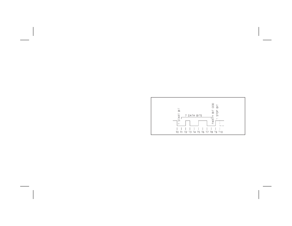
The format that the Gemini 5200 will accept is: 1 start bit, 7 data bits, 1 odd
parity bit, and 1 stop bit. The Baud Rates that are available are: 300, 600, 1200,
and 2400.
The selection of the Baud Rate is done by setting DIP switches. Refer to the
“Current Loop Installation” section, for set-up instructions.
-23-
FIG. 1: DATA FORMAT-10 BIT FRAME [300, 600, 1200, 2400 Baud]