Red Lion GEMINI 52 User Manual
Page 29
CURRENT LOOP INSTALLATION
WIRING CONNECTIONS
When wiring the 20 mA current loop, remove the 7-position terminal block
(TBD), located on the right side of the top board. Refer to the numbers listed with
the terminal descriptions below or on the top label, and install each wire in its
proper location on the terminal block. When all connections are made, replace
the terminal block into its proper location.
It is recommended that shielded (screened) cable be used for serial
communications. This unit meets the EMC specifications using Alpha #2404
cable or equivalent. There are higher grades of shielded cable, such as, four
conductor twisted pair, that offer an even higher degree of noise immunity.
TERMINAL DESCRIPTIONS FOR TERMINAL BLOCK TBD
1. -20 mA SRC (COMM.) - Common for 20 mA SRC and Print Request
terminal.
2. PRINT REQUEST - The Print Request Terminal is pulled low to request the
Gemini 5200 to transmit according to the Print Options mode that has been
selected. (Minimum Activation time = 25 msec.)
3. +20 mA SRC - The 20 mA SRC terminal provides the source current for one of
the loops.
4. SO- (Serial Out-)
5. SO+ (Serial Out+)
The Gemini 5200 transmits the requested data on these terminals. They are
connected in series to the receive input of the device to be connected.
6. SI- (Serial In-)
7. SI+ (Serial In+)
The Gemini 5200 receives commands on these terminals. They are connected
in series with the transmit or output terminals of the device to be connected.
Note: The serial input terminals must be held in the mark condition (current on)
in order for the Gemini 5200 to respond to a Print Request terminal activation.
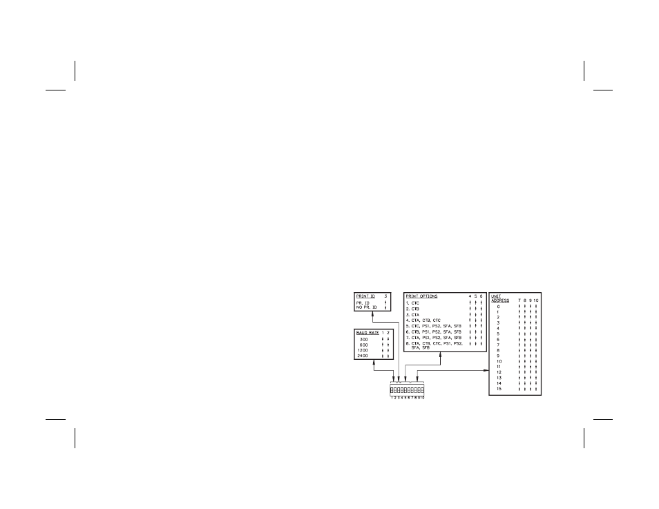
SERIAL DIP SWITCH SET-UP
The Serial DIP switches are accessible through the side of the Gemini 5200. A
list of the DIP switch positions and their functions are shown in Figure 4.
BR0 & BR1, BAUD RATE - Set-up is shown in Figure 4. When changing the
Baud Rate, the unit should be powered-down and then powered back up again.
The unit will only recognize a baud rate change upon power-up, after
activating the “Print Request” terminal or after a few characters have been
sent at the new baud rate (If the two previous conditions have not occurred, the
Gemini will see the characters as erroneous and it will check the baud rate and
set itself to operate at the new rate).
PR.ID - PRINT ID. - When this switch is in the up position, the Gemini 5200
will print the unit address, data value ID and the data value when a
transmission is requested. The unit will also insert a 400 msec delay between
transmissions when the “P” command or Print Request terminal is used. This
switch position is generally used when the unit is connected with a printer.
When the switch is in the down position, the Gemini 5200 will transmit only the
data value, without the unit address and data ID. The 400 msec delay, described
above, will not be inserted. This switch position usage is intended for applications
where the Gemini is communicating with a computer. In these circumstances
printing the address and value ID and inserting a 400 msec print delay is usually
unnecessary and needlessly slows down communication throughput.
PC0, PC1, & PC2, PRINT OPTIONS - Used to control which values are
printed out when the Print Request terminal is activated or when the Transmit
per Print Options command “P” is sent to the Gemini 5200.
AD0, AD1, AD2, & AD3 UNIT ADDRESS - These switches are used to give
each unit a separate address when more than one unit is connected in the Loop.
See Figure 4, for Switch Set-up.
-27-
FIG. 4: DIP SWITCH SET-UP