Red Lion GEMINI 52 User Manual
Page 38
Notes:
1. SENSOR VOLTAGE AND CURRENT
The +12 V sensor supply voltage on the “DC OUT” terminal is nominal with
+/-25% variation due to line and internal load variations. All RLC sensors
will accommodate this variation.
2. HI/LO FRQ SELECTION
The HI/LO FRQ selection switch must be set on “LO FRQ” when switch
contacts are used to generate rate input signals. Since the “LO FRQ” mode
also provides very high immunity against electrical noise pickup, it is
recommended that this mode also be used, whenever possible, with electronic
sensor outputs. The “LO FRQ” mode can be used with any type of sensor
output, provided pulse widths never decrease below 5 msec, and the rate does
not exceed 100 cps.
3. V
IL
and V
IH
levels given are nominal values +/-10% when the voltage on “DC
OUT” terminal is +12 VDC. These nominal values will vary in proportion to
the variations in the “DC OUT” terminal voltage, which are caused by line
voltage and load changes.
4. When shielded cable is used, the shield should be connected to “COMM.” at
the counter and left unconnected at the sensor end.
5. Inputs A and B can accept source pulses from other circuits up to +28 V in
amplitude. For voltages above +28 V, a limiting resistor and zener diode
should be used to limit the voltage at the input.
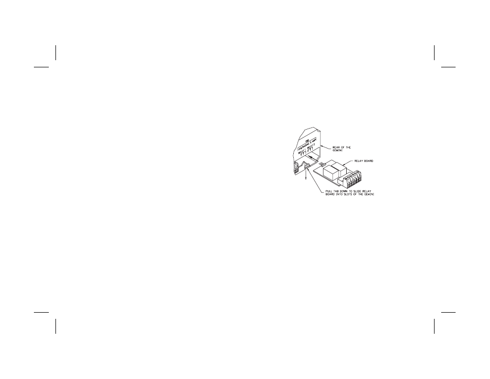
INSTALLATION & REMOVAL OF THE RELAY BOARD
To install the relay board, locate the relay opening at the lower right-hand
corner, on the back of the Gemini 5200. Pull the tab down while sliding the board
into the two slots in the housing. The relay board will seat into the unit, allowing
the tab to return to its original position. To remove the relay board, pull down on
the tab just enough to allow the relay board to slide out. Grasp the six terminal
connector and pull to remove the board.
-36-