HP Compaq StorageWorks TL881 DLT Mini-Library User Manual
Page 75
3-6 Compaq TL881 Minilibrary System Users Guide
1
2
SHR-1235
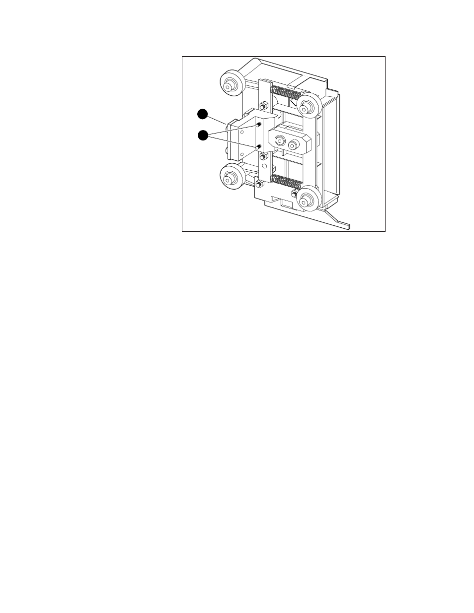
Figure 3-3. Car Rear View Showing Belt Block
1 Belt block
2 Captive screws
The belt block comes fastened to the back of the car with two captive screws.
Carefully note the orientation of the block with respect to the car, as shown in
Figure 3-3.
Orientation of Parts During Assembly
To determine the orientation of an extension section, examine the flanges on
the edges of the section, and note that they are dissimilar. Position the section
so that its orientation matches that of the elevator base.
Figure 3-4 shows a typical Pass-Thru mechanism assembly. The motor drive
section always goes on top, and the base section with the idler pulley always
goes on the bottom. Extension sections are mounted between the motor drive
section and the base section. All sections are joined together with tie bars. For
systems up to four modules, two support braces are needed, one attached to the
motor drive and one to the base section. For larger systems, a third support
brace should be mounted near the center of the Pass-Thru mechanism.
Preparing to Assemble the
Pass-Thru Mechanism
You will need a clean, flat work area such as a table or work bench. The
surface should be long enough to support the full height of the Pass-Thru