I/o modules – HP 4000.6000.8000 Enterprise Virtual Arrays User Manual
Page 21
8. Power supply 2
7. Blower 2
10. Status indicators (EMU, enclosure power, enclosure
fault)
9. I/O module A
I/O modules
Two I/O modules provide the interface between the drive enclosure and the host controllers. See
. They route data to and from the disk drives using Loop A and Loop B, the
dual-loop configuration. For redundancy, only dual-controller, dual-loop operation is supported.
Each controller is connected to both I/O modules in the drive enclosure.
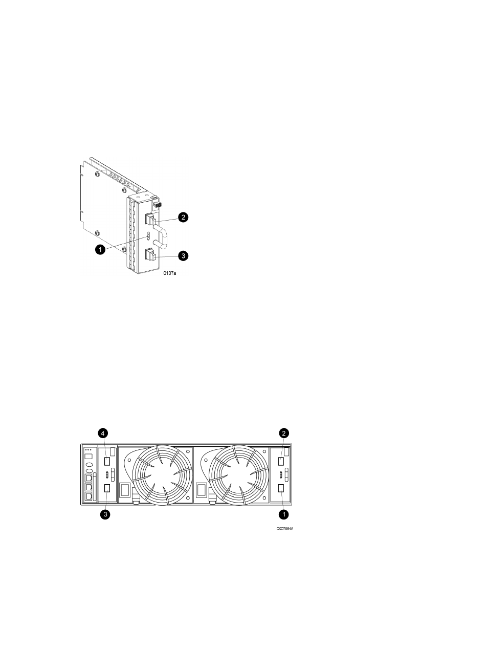
Figure 7 I/O module
1. Status indicators (Upper port, Power, and Lower port)
2. Upper port
3. Lower port
The I/O modules are functionally identical, but are not interchangeable. Module A can only be
installed at the right end of the enclosure, and module B can only be installed at the left end of the
enclosure. See
.
Each I/O module has two ports that can both transmit and receive data for bidirectional operation.
Activating a port requires connecting a FC cable to the port. The port function depends upon the
loop. See
Figure 8 Input and output ports
2. Loop A upper port
1. Loop A lower port
4. Loop B upper port
3. Loop B lower port
Fibre Channel drive enclosures
21