Connection – SilentKnight VisorAlarm Plus 2U User Manual
Page 16
VISORALARM - Installation
II - 14
Doc.DM374-I
Ver.1.0
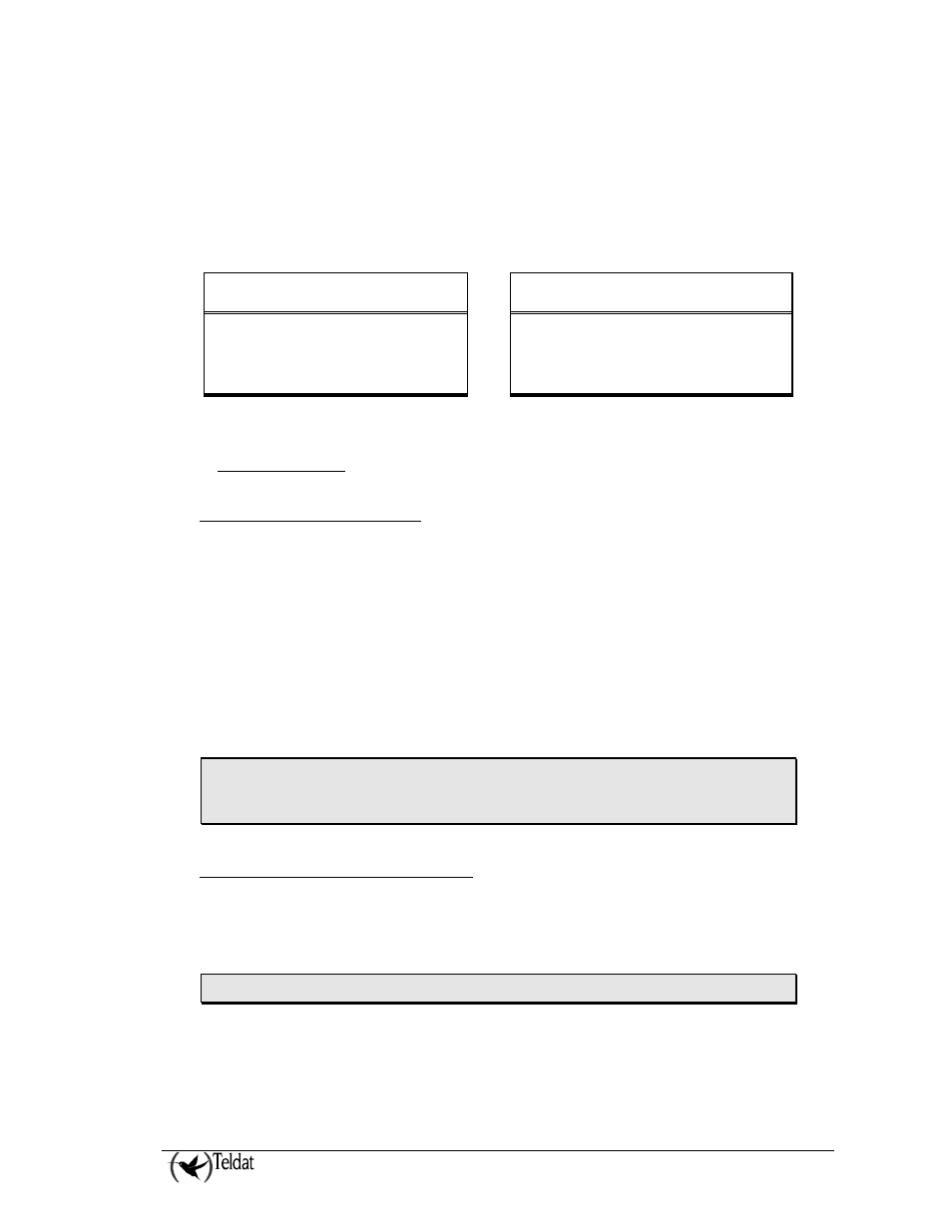
Figure 5. 19” rack installation and device power connections
WARNING: Electric supply current, telephone and communication cables are dangerous. To
prevent electric shock while installing, moving or opening the device covers, cables should
be disconnected and connected as follows:
To connect the VisorALARM PLUS
2U
To disconnect the VisorALARM PLUS
2U
•
Make sure that the device power supply
switch is OFF.
•
Switch off the device.
•
Connect all the data cables.
•
Disconnect the power supply cable.
•
Connect the power supply cable.
•
Disconnect the data cables.
•
Switch on the device.
1.2. Connection
a) LAN Ethernet connection
The device has two Ethernet 100baseT LAN interfaces to connect to the IP network
.
This LAN
interface has a female RJ45 connector in order to connect to the Ethernet 10BaseT networks through a
shielded twisted pair (STP) or unshielded (UTP) cables. These cables are not supplied with the
equipment; please consult your supplier with regard to this.
Depending on the design of the Network, the connection is carried out through a HUB or directly to
another terminal device Ethernet interface through a crossover cable (please consult your supplier for
information on crossover Ethernet cables).
When the VisorALARM is connected to the Ethernet through the LAN1 connector, the LED on the
front panel labeled LAN1 will light up in green. If there is no connection, the LED will light up in red.
The same thing will happen with the other LAN2 Ethernet connector. Please note that in the factory
configuration only the LAN1 connection is configured.
IMPORTANT: For UL listed installations it is mandatory to connect the VisorALARM
ethernet interface to the ethernet building installatation through the device ESD-100
ethernet data line protector (Alerton Technologies, UL listed UUKL.S8105).
b) Connecting to the alarm server
Data connection to the alarm automation server is carried out through the serial interface labeled AUT
in the device. This serial interface complies with the V.24 norm, behaves as DCE and has a female
DB25 connector. You need to use a DB25 male serial cable to a DB9 female in order to connect to the
server.
IMPORTANT: Do not use a null modem cable.
When the VisorALARM is connected to the Automation Server, the LED on the front panel labeled
AUT will light up in green. If there is no connection, the LED will light up in red.