7 setting of write protect switch, 8 power failure, 2 adjustment for manual mode – Yokogawa digitalYEWFLO (DY) User Manual
Page 97: 1 low cut adjustment, 2 zero tuning, Setting of write protect switch -3, 8 power, Failure, Adjustment for manual mode -3 10.2.1 low, Adjustment
<10. OPERATION>
10-3
IM 01F06A00-01EN
10.1.7 Setting of Write Protect Switch
By setting the write protect function to “Protect”, it is
possible to prevent the overwriting of parameters.
Write protection can be carried out using either the
hardware switch on the CPU board (i.e., Switch
2) or software parameter settings. If either of
these items is set to “Protect”, the overwriting of
parameters will be prohibited.
NOTE
If the hardware switch is set to “Protect”, it
will not be possible to overwrite parameters;
furthermore, this condition will be maintained
until the switch is set to “Enable”.
For more details regarding usage of the write
protect function and the software’s parameter
switches, refer to Section 8.9 “Software Write
Protect” or Section 9.9 “Software Write Protect.”
Table 10.2 Setting pin for Write Protect
Pin position
CPU error
burnout direction
N
Y
Enable
N
Y
Protect
10.1.8 Power Failure
When a power failure occurs, the totalized value
will be protected by EEPROM (Electrically Erasable
Programmable ROM). But during a power failure,
the vortex fl owmeter stops and also the totalizing
will stop.
After a power is recovered, the vortex fl owmeter
and the totalizing start to work automatically.
EEPROM doesn’t need a battery for backup.
10.2 Adjustment for Manual Mode
digitalYEWFLO does not need the initial adjustment
because digitalYEWFLO is always adjusted by itself
automatically.
These adjustments should be done in case that
indicator reads over zero at zero fl ow.
10.2.1 Low Cut Adjustment
Adjust to noise elimination or zero fl ow in the low
fl owrate (or low frequency) range.
The settable range for low cut fl owrate is to half of
minimum fl owrate.
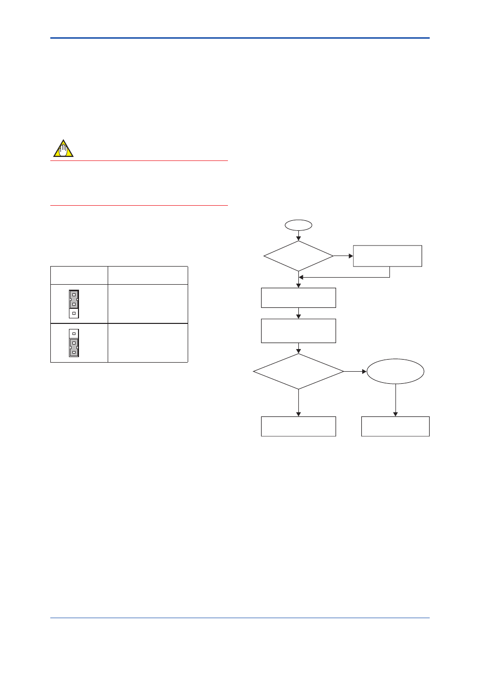
10.2.2 Zero Tuning
This adjustment should be done according to a fl ow
fi gure shown below.
START
Is it zero flow?
No
No
Stop flow to be zero
Yes
Yes
Set "TUNING AT ZERO"
of "K25:N.B MODE"
Wait more than 30 seconds
Ensure the complete of the
tuning function.
Is indication reads zero
at zero flow?
Finishing the tuning
functios
Retry the tuning and ensure
the pipeline conditions?
Ensure TLA value
in "K10: TLA"
F1003.ai
Figure 10.3 Tuning Flow
If this adjustment is executed, the following value is
changed.
K25:N.B MODE = MANUAL
K26:NOISE RATIO=Constant value
Minimum fl owrate is increased when TLA value is
changed form initial value.