2 selection of wires, 3 connection, Selection of wires -2 – Yokogawa digitalYEWFLO (DY) User Manual
Page 21: Important
<4. WIRING>
4-2
IM 01F06A00-01EN
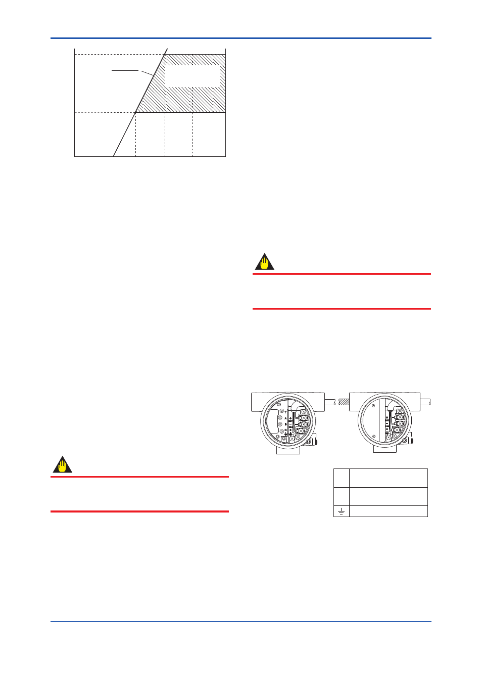
R=
E–10.5
0.0236
250
600
10.5
16.4
24.7
30
42
Power Supply Voltage E (V)
Communication
Applicable range
BRAIN and HART
Load resistance R (
)
F0401.ai
Figure 4.1
Relationship between Power Supply
Voltage and Load Resistance (4 to 20
mA DC Output)
(2) Pulse output and Alarm, Status Output
This version uses three wires between the
converter and the power supply. A DC power
and load resistance are required, and pulse
output is connected to a totalizer or an electric
counter. Low level of the pulse output is 0
to 2V. No communication is possible over
a transmission line. Communication via the
amplifi er board is always possible irrespective
of the wiring condition.
(3) Simultaneous Analog-Pulse Output
When using digitalYEWFLO in the
simultaneous analog -pulse output mode, the
communicable distance of the transmission
line is restricted on the wiring method. Table
4.1 shows the examples of connection for this
output mode. Communication via the amplifi er
board is always possible irrespective of the
wiring condition.
IMPORTANT
For pulse output and the simultaneous analog-
pulse output ,use the load resistance. Refer to
Table 4.1.
4.2 Selection of Wires
The following should be taken into consideration
when selecting cables for use between the
converter and distributor.
(1) Use 600V PVC insulated wire or equivalent
standard wire or cable.
(2) Use shielded wire in areas susceptible to
electrical noise (both analog and pulse output
versions).
(3) In areas with high or low ambient temperatures,
use wires or cables suitable for such
temperatures.
(4) In atmospheres where oils or solvents,
corrosive gases or liquids may be present, use
suitable wires or cables.
(5) Use cable which withstand temperature up to
+60°C and more, when ambient temperature is
more than +60°C.
IMPORTANT
For the remote type, use DYC signal cable
to connect the converter and remote type
fl owmeter(DY-N).
4.3 Connection
Table 4.1 shows the connection sample of
connection for power supply and load resistance.
The terminal position of each connection is shown
in Figure 4.2.
Integral type
Remote type
F0402.ai
4 to 20 mA DC Output Power Supply
and Output Signal Terminals
Supply
+
–
Pulse Output Terminal
Pulse
+
Grounding Terminal
Figure 4.2
Terminal Position