5 mounting procedures, 5 mounting, Procedures – Yokogawa digitalYEWFLO (DY) User Manual
Page 16: Caution, 5 mounting procedures warning
<3. INSTALLATION>
3-6
IM 01F06A00-01EN
3.4 Cryogenic and High Process
Temperature Version
Insulation
When you are using Cryogenic and High Process
Temperature version of digitalYEWFLO Vortex
Flowmeter (Option code: /HT, /LT), refer to following
contents.
Installing Cryogenic Version
For cryogenic applications, use stainless steel
mounting bolts and nuts to install the fl owmeter.
These can be ordered separately from
YOKOGAWA. Cover the fl owmeter body with
heat insulating material so that the fl owmeter
can be maintained at ultra-low temperatures.
Maintenance for Cryogenic Applications
DY/LT uses special materials that produce
vortex fl owmeter for cryogenic applications.
When you are replacing a shedder bar, specify
Cryogenic Version shedder bar. To avoid
condensing in the terminal box, ensure that the
wire connecting port is well sealed.
F0308.ai
Bracket
Cold insulating material
Installing High Process Temperature
Version
Installation of the fl owmeter is the same as the
standard type. Cover the fl owmeter body with
heat insulating material following instruction of
“CAUTION”.
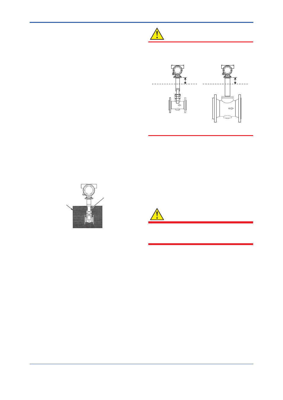
CAUTION
Keep the upper limit of heat insulating material to
prevent overheating of the terminal box.
Seal the Heat-Insulator to avoid hot-air leakage.
UPPER LIMIT OF
Heat-Insulator
UPPER LIMIT OF
Heat-Insulator
50mm min.
50mm min.
Nominal Size: 100mm or under
Nominal Size: 150mm or over
F0309.ai
Maintenance for High Process
Temperature Applications
DY/HT uses special materials that produce
vortex fl owmeter for High Process Temperature
applications When you are replacing a
shedder bar or a gasket, specify High Process
Temperature Version.
3.5 Mounting
Procedures
WARNING
The Vortex Flowmeter is a heavy instrument.
Please be careful to prevent persons from
injuring whin it is handled.
Before installing the instrument verify the following.
The direction of fl ow should match to the arrow
mark on the instrument body. When changing the
orientation of the terminal box, refer to Chapter 11
“MAINTENANCE.”
1. Installation of Vortex fl owmeter of the wafer and
fl ange type is shown in Table 3.3.
When installing the wafer type vortex fl owmeter,
it is important to align the instrument bore with
the inner diameter of the adjacent piping.
To establish alignment, use the four collars
supplied with the instrument.