Yokogawa digitalYEWFLO (DY) User Manual
Page 22
<4. WIRING>
4-3
IM 01F06A00-01EN
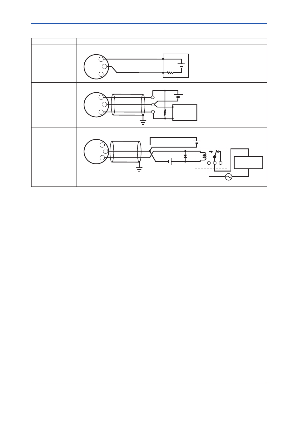
Table 4.1 (a) The wiring example for the analog and pulse and status, alarm output.
Connection
Description
Analog Output
In this case, Communication
is possible (up to a distance
of 2km when a CEV cable is
used.)
digitalYEWFLO Electrical Terminal
250
Ω
24V DC
+
–
Distributor
PULSE
SUPPLY
+
–
+
Pulse Output
In this case, No
communication is possible.
This supply voltage requires
a power sourse with a
maximum output current of
no less than E/R+25mA.
R
E
digitalYEWFLO Electrical Terminal
Use the Three-wire shielded cable.
Electric counter
*1
*2
Shielded Cable
PULSE
SUPPLY
+
–
+
Status Output
Alarm Output
In this case,
No communication is
possible.
Use the Three-wire shielded cable.
Shielded Cable
PULSE
SUPPLY
+
–
+
Magnetic
valve
AC power supply
External Power supply
30V DC, 120mA max
(Contact Rating)
digitalYEWFLO Electrical Terminal
E
Relay
*1: To avoid the infl uence of external noise, use an electric counter which fi ts to the pulse frequency.
*2: Resistor is not necessary in case of an electric counter which can receive contact pulse signal directly.