2 indicator removal and rotation, 3 amplifier unit removal, 4 amplifier unit assembling – Yokogawa digitalYEWFLO (DY) User Manual
Page 101: Indicator removal and rotation -3, 3 amplifi er unit removal important, 4 amplifi er unit assembling important, 2 indicator removal and rotation important, Caution
<11. MAINTENANCE>
11-3
IM 01F06A00-01EN
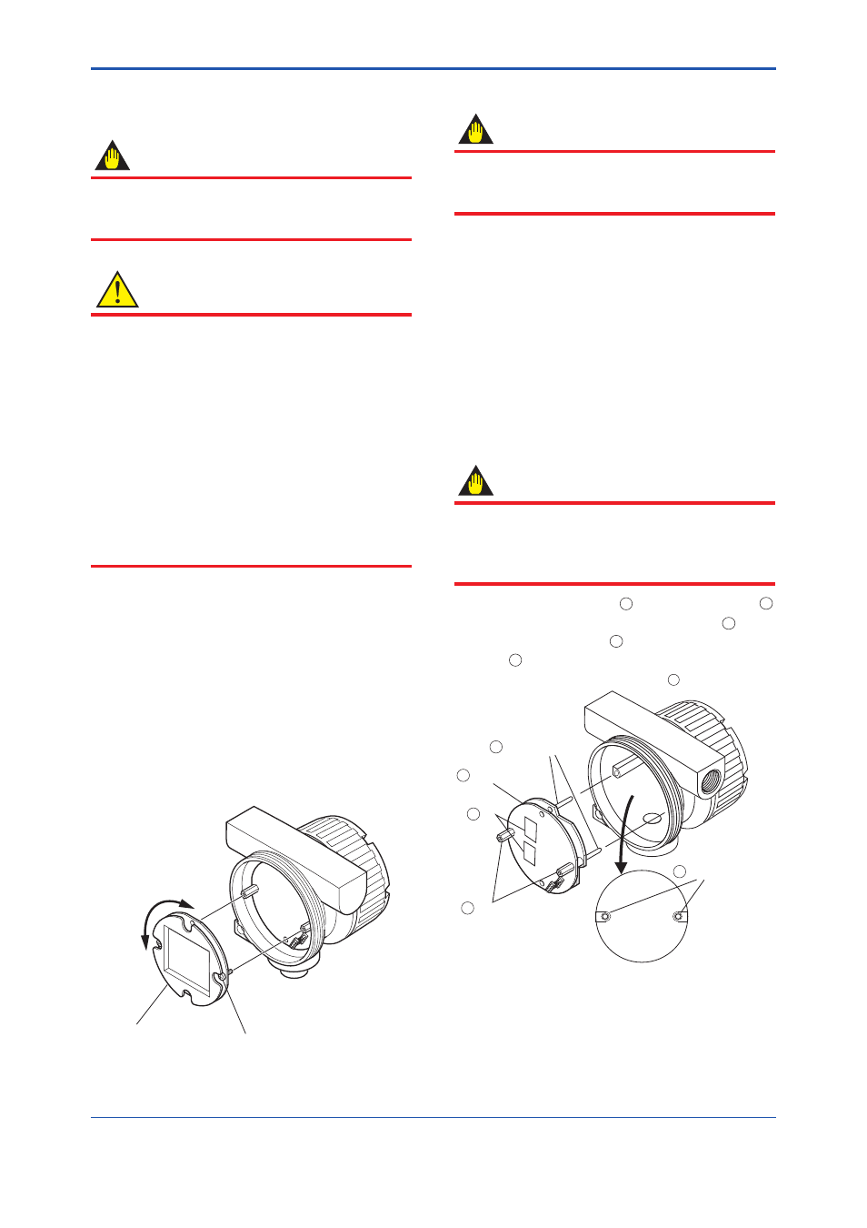
11.3 Amplifi er Unit Removal
IMPORTANT
Do not turn the amplifi er unit for removal
or assembling. The connector pins may be
damaged.
(1) Turn the power OFF.
(2) Remove the converter cover.
In case of the Explosion protected type, remove
the cover after unlock the Locking Screw.
(3)
Remove the indicator according to the
procedures described in Section 11.2 “Indicator
Removal and Rotation.”
(4)
Loosen the terminal screws and remove the
amplifi er unit.
11.4 Amplifi er Unit Assembling
IMPORTANT
The amplifi er unit must be assembled keeping
the procedure as follows. Amplifi er may not
operate normally when the procedure does not
keep.
(1) Put two Mounting Pins
1
into Mounting Holes
2
.
(2) Push the head of two Mounting Screws
4
lightly.
(3)
Push head of two IC
5
and mount the Amplifi er
Unit
3
.
(4) Tighten two Mounting Screws
4
.
F1103.ai
Amplifier Unit
Mounting Screws
Mounting Holes
Mounting Pins
IC
1
2
3
4
5
Figure 11.2 Removing and Reinstalling the
Amplifi er Unit
11.2 Indicator Removal and
Rotation
IMPORTANT
For Explosion protected type, modifi cation by
the user is prohibited. It is prohibited to add or
remove the indicator.
CAUTION
• For
fl ameproof type, move vortex fl owmeter
to non-hazardous area fi rstly, then remove
and rotate the indicator. The instrument must
be restored to its original condition.
• For
fl ameproof type, when you open the
cover, turn the locking screw to the right and
unlock. When you close the cover, be sure to
turn the locking screw to the left and lock.
• For
TIIS
fl ameproof type, refer to
“INSTALLATION AND OPERATING
PRECAUTIONS FOR TIIS FLAMEPROOF
EQUIPMENT” at the end of this User’s
manual.
(1) Turn the power off.
(2) Remove the cover.
In case of the Explosion protected type, remove
the cover after unlock the Locking Screw.
(3)
For the indicator, disconnect the cable
connector from the amplifi er unit.
(4)
Loosen the two indicator mounting screws
using a Phillips screwdriver.
(5) Pull out the indicator.
(6)
Reinstall the indicator in the reverse order to
its removal (above) and secure the mounting
screws.
F1102.ai
Indicator
90°
Indicator Mounting Screws
(2PCS)
Figure 11.1 Removing and Reinstalling the
Indicator