Type (/mv) -10 – Yokogawa digitalYEWFLO (DY) User Manual
Page 120
<13. GENERAL SPECIFICATIONS>
13-10
IM 01F06A00-01EN
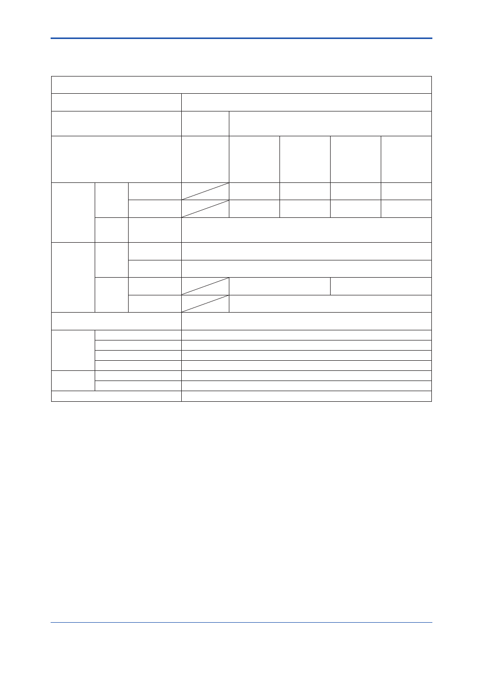
13.3.1 Option Multi-Variable (Built-In Temperature Sensor) Type (/MV)
This options is the same as standard specifi cation except the following items.
Multi-Variable (Built-in Temperature sensor) Type (Option Code: /MV) (Note1)
High Process Temperature Version Multi-Variable Type (Option Code: /HT/MV)
Model code
DY025 to DY100 (Wafer)
DY025 to DY200 (Flange)
Function (Note2)
Temperature
Indication /
Ouput
Mass Flow Calculation
(Volmetric fl owrate at Standard Condition for GAS)
Fluid
LIQUID, GAS,
SATURATED
STEAM,
SUPERHEATED
STEAM
(Note3)
SATURATED
STEAM
(Note4)
SUPERHEATED
STEAM
(Note5)
GAS
(Note6)
LIQUID
(Note7)
Mass Flow
Calculation
Calculation
Temperature
Range
Option Code:
/MV
+100 to +250°C +100 to +250°C
-29 to +250°C
-29 to +250°C
Option Code:
/HT/MV
+100 to +330°C +100 to +400°C
-29 to +400°C
-29 to +400°C
Accuracy
(Note8)
Option Code:
/MV
/HT/MV
(Note8)
Temperature
Temperature
Range
Option Code:
/MV
-29 to +250°C
Option Code:
/HT/MV
-29 to +400°C
Accuracy
Option Code:
/MV
±0.5°C(less than +100°C)
±0.5% of rate (+100°C or more)
±1°C(less than +100°C)
±1% of rate (+100°C or more)
Option Code:
/HT/MV
±1°C (less than +100°C)
±1% of rate (+100°C or more)
Temperature Response
(50% Response)
60 sec
(Churning Underwater)
Output
Analog Output
Select from Flow Rate or Temperature (Note9)
Pulse Output
Flow Rate: Same as Standard Type
Alarm Output
Alarm Output same as Standard Type and Temperature Sensor Error, etc.
Status Output
Flow Switch (Flow Rate): Same as Standard Type
Display
Upper
Select from Flow Rate (%, Engineering Unit) or Temperature (%) (Note10)
Lower
Select from Total Rate or Temperature (°C,°F) (Note11)
Remote Type
Select Vortex Flow Converter DYA-/MV and Signal Cable DYC-/MV (Note12)
(Note1) Multi-Variable Type /MV can not be combined with Cryogenic Version /LT.
(Note2) Temperature measurement may be affected by installation conditions, such as thermal insulation of piping or the temperature
distribution of the fl uid. Refer to Section 3.2 “Piping Precautions” for thermal insulation of piping. When measuring mass
fl ow of saturated steam, superheated steam thermal insulation of piping may be required.
(Note3) Measured temperature is not used for fl ow measurement.
(Note4) Mass fl ow rate is calculated from density calculated with density at the mesuared temperature derived by the built-in saturated
steam table.
(Note5) Mass fl ow rate is calculated with the density at the measured temperature derived by the built-in steam table. For mass fl ow
calculation of superheated steam, operating pressure is used as constant value.
(Note6) Volumetric fl ow rate is calculated by temperature/pressure compensation. For volumetric fl ow calculation of gas, operating
pressure and pressure at standard/normal condition are used.
(Note7) Mass fl ow rate is calculated with density compensated by the secondary formula of measured temperature. Operating
density is used as a base density and the 1st and 2nd coeffi cients have to be set.
(Note8) Refer to Section 13.5 “Detailed Accuracy”
(Note9) The factory setting is the fl ow rate output. When the temperature output is required, it is necessary to change the parameter.
(Note10) In case of indicating the temperature %, the display indicate not only “%” but also “t”. ( “t” means temperature).
(Note11) Default setting is “Temperature” but “Total” is set when the total rate is specifi ed in sizing data.
(Note12) In case of remote type, option code /MV is necessary for both Vortex Flow Converter (DYA) and Signal Cable (DYC).
To correct the temperature error due to signal cable length, parameter setting of the signal cable length to Vortex Flow
Converter (DYA) is required.