3 iecex, 3 iecex warning, Warning – Yokogawa digitalYEWFLO (DY) User Manual
Page 158
<14. EXPLOSION PROTECTED TYPE INSTRUMENT>
14-7
IM 01F06A00-01EN
14.3 IECEx
WARNING
• Only trained persons use this instrument in
industrial locations.
• Electrostatic charge may cause an explosion
hazard.
Avoid any actions that cause the generation
of electrostatic charge, such as rubbing with
a dry cloth on coating face of product.
(1) Technical Data
• Flameproof
Applicable Standard : IEC60079-0: 2007-10,
IEC60079-1: 2007-04
Certifi cate : IECEx DEK 11.0077X
Type of Protection:
Ex d IIC T6…T1 Gb (Integral Type Vortex
Flowmeter and Remote Type Vortex Flow
Detector)
Ex d IIC T6 Gb (Remote Type Vortex Flow
Converter)
Specifi cation of Protection:
Process
Temperature:
(Integral Type Vortex
Flowmeter and Remote
Type Vortex Flow
Detector)
Temperature Class
Process Temperature
T6
-29°C to +80°C
T5
-29°C to +100°C
T4
-29°C to +135°C
T3
-29°C to +200°C
T2
-29°C to +300°C
T1
-29°C to +450°C
*1 Note: Use /HT version above 250°C
Temperature Class: T6 (Remote Type Vortex Flow
Converter)
Ambient Tamp.:
–29 to +60°C (Integral Type Vortex Flowmeter
and Remote Type Vortex Flow Detector)
–40 to +60°C (Remote Type Vortex Flow
Converter without indicator)
–30 to +60°C (Remote Type Vortex Flow
Converter with indicator)
Power Supply: 10.5 to 42Vdc max.
Output Signal: Current Output; 4 to 20mAdc
Pulse output; On=2Vdc, 200mA
Off=42Vdc,
4mA
Special Fastener: Class A2-50 or more
Special conditions for safe use
1. For process temperatures above 250°C the fl ow
meters of the /HT version must be used.
(2) Installation
WARNING
• All wiring shall comply with local installation
requirements and local electrical code.
• Use the suitable heat-resisting cables (over
90°C) for the digitalYEWFLO Model DY
Series Vortex Flowmeter when the ambient
temperature exceeds 60°C and/or the
process temperature exceeds 200°C.
• The cable entry devices shall be certifi ed in
type of protection fl ame proof enclosure “d”
and suitable for the conditions of use and
correctly installed.
• Unused apertures shall be closed with
certifi ed blanking elements in type of
protection fl ame proof enclose “d”.
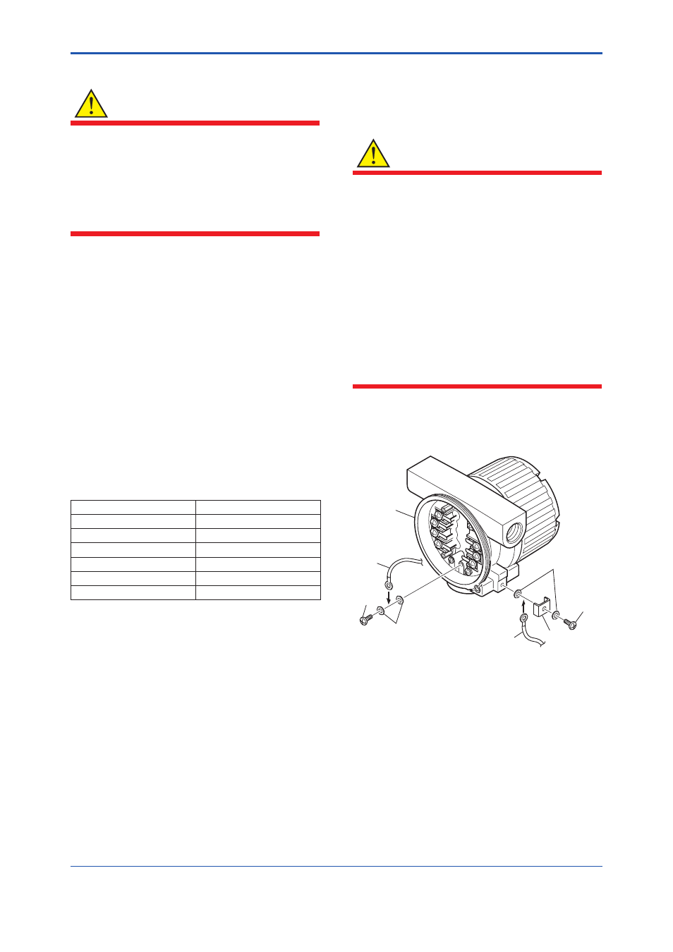
The grounding terminals are located on the inside
and outside of the terminal area.
Connect the cable to grounding terminal in
accordance with wiring procedure (1) or (2).
Case
Cable
Screw
(1) Internal grounding terminal
(2) External grounding terminal
Washer
Washer
Cable
Clamp
Screw
F1406.ai
Figure 14.2 Wiring Procedure for Grounding
Terminals