Warning, 3) operation, 4) maintenance and repair – Yokogawa digitalYEWFLO (DY) User Manual
Page 154: 6) electrical connection
<14. EXPLOSION PROTECTED TYPE INSTRUMENT>
14-3
IM 01F06A00-01EN
(3) Operation
WARNING
• Wait 3 min. after power is turned off, before
opening the covers.
• Take care not to generate mechanical
spark when access to the instrument and
peripheral devices in hazardous locations.
(4) Maintenance and Repair
WARNING
• The instrument modifi cation or parts
replacement by other than authorized
representative of Yokogawa Electric
Corporation is prohibited and will void the
certifi cation.
(5) Installation Diagram of Intrinsically safe
(and Note)
DY (flowmeter)
SUPPLY
PULSE
Safety barriers
[Integral type]
Note: In any safety barrier used output current must be limited
by a resistor ‘R’ such that Io=Uo/R
Electric data:
Supply and Output Circuit (SUPPLY
1
and
2
, PULSE
1
and
2
)
Maximum Input Voltage Ui: 30V
Maximum Input Current Ii: 165mA
Maximum Input Power Pi: 0.9W
Internal Capacitance Ci: 6nF
Internal Inductance Li: 0.15mH
+
-
+
-
+
-
+
-
+
-
+
-
+
-
+
-
+
-
+
+
-
+
[Remote type without built-in Temperature sensor]
DYA (flowmeter)
SUPPLY
PULSE
A
B
T
(
*1)
C
A
B
T
Safety barriers
DY-N (flowmeter)
DYC: Signal cable
Hazardous
Non Hazardous
Location
Hazardous
Non Hazardous
Location
F1402.ai
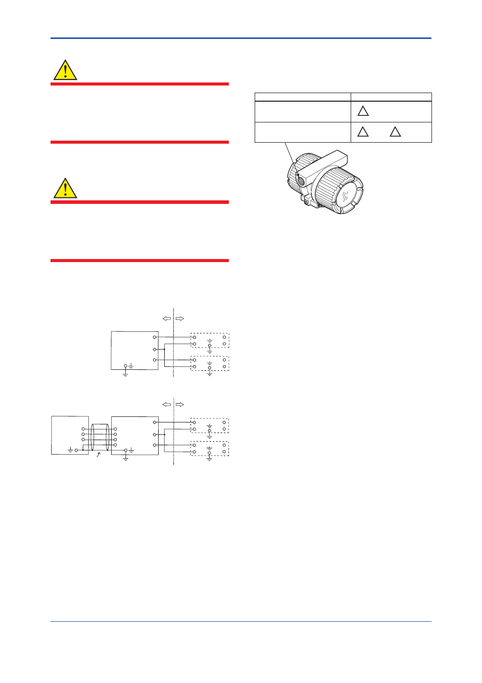
(6) Electrical Connection
The type of electrical connection is stamped near
the electrical connection port according to the
following codes.
F1403.ai
Screw size
ISO M20 X 1.5 female
ANSI 1/2-14NPT female
!
M
!
N
or
!
A
Marking