5 vortex shedder removal, Vortex shedder removal -4, 5 vortex shedder removal caution – Yokogawa digitalYEWFLO (DY) User Manual
Page 102: Important
<11. MAINTENANCE>
11-4
IM 01F06A00-01EN
11.5 Vortex Shedder Removal
CAUTION
• Disassemble work should be done only for
error occurrence.
• Only expert engineer or skilled personnel are
permitted to open the cover.
• When the vortex shedder is disassembled,
and empty the fl ow tube before the gasket
must be replaced with a new one.
• Output error may cause when the shedder
bar is not restored correctly.
• For Explosion proof type, move vortex
fl owmeter to non-hazardous area fi rstly, then
do the assemble work.
(1)
For nominal size 15 to 100mm (1/2 to 4
inch), remove the converter cover or terminal
box according to the following (2) to (5). For
nominal size 150 to 400mm (6 to 16 inch), this
procedure is not necessary.
(2)
For integral type, remove the converter cover.
For remote type, remove the terminal cover.
For integral type, loosen the hexagonal screw
on the Amplifi er unit, then remove the amplifi er
unit. Remove the indicator fi rst, in case the
device has it.
(3)
For integral type, remove the Shielded cover
back Amplifi er unit. In case of following
Explosion proof type, loosen the locking screw
on the converter case or terminal box.
Explosion proof type: TIIS Flame proof, ATEX
Explosion proof, IECEx
Flame proof
(4)
Remove the Leadwire by loosening a screw on
the terminal strip.
(5)
Loosen the bracket mounting bolts and remove
the converter case or terminal box together
with the bracket. Be careful not to damage the
leadwires of the vortex shedder assembly.
(6)
Loosen the vortex shedder assembly mounting
bolts (2 to 10 pcs) and remove the vortex
shedder assembly.
(7)
When reassembling the vortex shedder
assembly, reverse above procedure. Confi rm
the following.
a. Replace to a new gasket.
b. The guide pin on the vortex shedder
mounting block meets the guide pin hole.
Refer to Figure 11.3.
Nominal size 150 to 400mm (6 to 16 inch)
has no guide pin.
c. The vortex shedder assembly is installed as
illustrated in Figure 11.3.
d. Tighten the sensor mounting bolts uniformly
and diagonally in three or four times. Refer to
Table 11.1 and Figure 11.4.
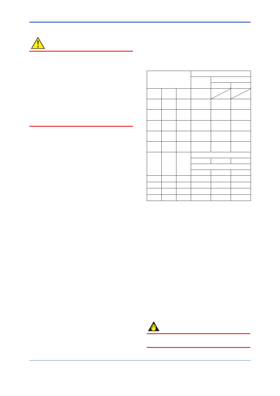
Table 11.1 Torque Value
Model Code
Torque Value UNIT: N.m
Standard,
/NC, /LT
/HT
A
B
DY015
DY025
/R1
DY040
/R2
16
DY025
DY040
/R1
DY050
/R2
12
18
12
DY040
DY050
/R1
DY080
/R2
12
18
12
DY050
DY080
/R1
DY100
/R2
18
27
18
DY080
DY100
/R1
DY150
/R2
32
48
32
DY100
DY150
/R1
DY200
/R2
49
74
49
DY150
DY200
/R1
—
shedder bar "E", "L", "X"
49
69
49
shedder bar "B"
60
90
60
DY200
—
—
69
98
69
DY250
—
—
157
210
140
DY300
—
—
157
210
140
DY400
—
—
160
240
160
/HT: High Process Temperature Version
/LT: Cryogenic Version
/NC: NACE Material
e. In case of High Process Temperature Version
(Option code: /HT), First time tighten bolts
with a torque wrench, applying the torque
specifi ed “A”. Next time loosen bolts then
again tighten bolts with a torque wrench,
applying the torque specifi ed “B”. For
loosing process, be sure not to loose bolts
completely.
f. Insert the leadwires (vortex shedder) through
the terminal box bottom hole and lower the
terminal box slowly until the bracket touches
the fl owmeter shoulder. Be sure to keep the
leadwires vertical while lowering the terminal
box.
g. After assembling, confi rm that there is no
leakage from the vortex fl owmeter.
IMPORTANT
Please tighten the screws/bolts uniformily and
observing the torque value in Table 11.1.