7 grounding, 7 grounding important – Yokogawa digitalYEWFLO (DY) User Manual
Page 28
<4. WIRING>
4-9
IM 01F06A00-01EN
(5)
Perform attachment of fl ameproof packing
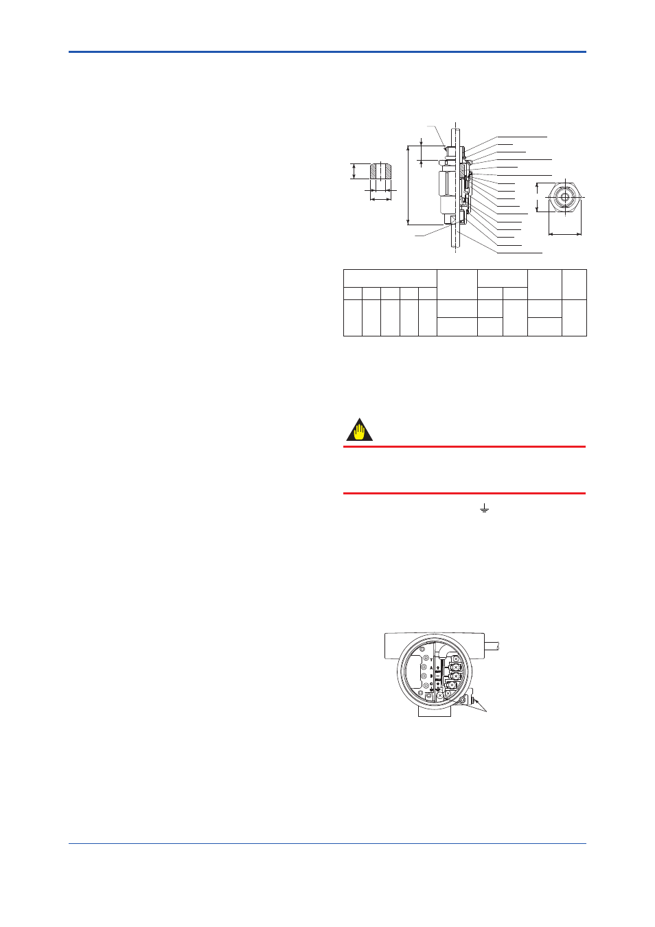
adaptor in the following ways. Refer to Figure
4.11.
(a) Loosen the locking screw and remove the
terminal box cover.
(b) Measure the cable outer diameter in two
directions to within 0.1 mm.
(c) Calculate the average of the two diameters,
and use packing with an internal diameter
nearest to this value. Refer to Table 4.2.
(d) Screw the fl ameproof packing adapter into
the terminal box until the O-Ring touches
the wiring port (at least 6 full turns), and
fi rmly tighten the lock nut.
(e) Insert the cable through the union nut, the
B. coupling, the clamp nut, the clamp ring,
the packing gland, the washer, the packing,
and the packing case, in that order.
(f) Insert the end of the cable into the terminal
box.
(g) Tighten the union cover to grip the cable.
When tightening the union cover, tighten
approximately one turn past the point where
the cable will no longer move up and down.
Proper tightening is important. If it is too
tight, a circuit break in the cable may
occur; if not tight enough, the fl ameproof
effectiveness will be compromised.
(h) Fasten the cable by tightening the clamp
nut.
(i) Tighten the lock nut on the union nut.
(j) Connect the cable wires to each terminal.
(6)
(a) Do not connect cables outdoors in wet
weather in order to prevent damage from
condensation and to protect the insulation.
(b) Do not splice the cable between the
fl owtube terminal and the converter if it is
too short. Replace the short cable with a
cable that is the appropriate length.
(c) The signal cables must be routed in
separate steel conduit tubes 16 (JIS C
8305) or fl exible conduit tubes 15 (JIS C
8309).
(d) Always route the power and output signal
cables in separate steel conduit tubes,
except when the power supply voltage is 24
V and four-core cables are used for wiring.
Keep conduits or fl exible tubes watertight
using sealing tape.
(7)
For the TIIS fl ameproof type with wiring using
a fl ameproof packing adapter, wire cables
through the packing adapters approved by
Yokogawa (option code: /G11 or /G12).
Unit : mm
(approx. inch)
F0414.ai
T1
T2
L
18
G
F
D
C
16.5
*Packing
(Choose from the table
below depend on cable
outside diameter)
Adapter body (M. Screw)
Packing case
Hexagon socket set screw
O-Ring
Packing *
O-Ring
O-Ring
Washer
Union nut
Packing gland
Clamp ring
Clamp nut
O-Ring
Hexagon socket set screw
B.coupling
Cable (user’s scope)
Size
Cable outer
diameter
Packing
dimensions
Identifi cation
mark
Weight
kg (lb)
T1
T2
C
D
L
F
G
G 1/2 G 1/2
35
(1.38)
39
(1.54)
94.5
(3.72)
ø8.0 to ш10.0
(ш0.31 to ш0.39)
ш10.0
(ш0.39)
ш20.0
(ш0.79)
16 8-10
0.26
(0.57)
ш10.0 to ш12.0
(ш0.39 to ш0.47)
ш12.0
(ш0.47)
16 10-12
Figure 4.12 Flameproof Packing Adapter (option
code: /G11, /G12)
4.7 Grounding
IMPORTANT
When a lightning protector (option code: /A) is
selected, use a grounding resistance of 10
Ω or
less.
(1)
The grounding terminals are located on the
inside and outside of the terminal area. Either
terminal may be used.
(2)
For pulse output version, ground the fl owmeter.
Also ground the shielded cable between the
converter and the pulse receiver.
(3)
Grounding should satisfy Class D requirements
(ground resistance 100
Ω or less).
(4) Use 600V PVC insulated wire for grounding.
Example: Integral Type
Grounding
Terminals
F0415.ai
Figure 4.13 Grounding Terminal