Yokogawa digitalYEWFLO (DY) User Manual
Page 113
<13. GENERAL SPECIFICATIONS>
13-3
IM 01F06A00-01EN
Status Output Function*:
Flow Switch:
In case fl ow rate decreases under the fl ow set
value,a status signal is output.
Status signal output mode can reverse (ON/
OFF).
Data Security During Power Failure:
Data (parameter, totalizer value, etc) storage
by EEPROM. No back-up battery required.
Correction:
Instrument Error Correction:
Vortex fl owmeter instrument errors can be
corrected by segment approximations.
Reynolds Number Correction:
Output error at Reynolds number 20000 or
less is corrected by using fi ve-break-point line-
segment approximation.
Gas Expansion Correction:
When measuring a compressibility gas and
steam, this expansion factor is useful to
correct the error at high velocity of fl ow (35m/s
or more).
Down-scale or Up-scale burn out.
In case a CPU or EEPROM failure occurs,
fl ow meter output the signal of Up-scale (21.6
mA or more).
Up-scale or Down-scale (3.6 mA or less) is
user-selectable through the fail mode alarm
jumper.
Indicator:
Flow rate (% or engineering units) or tem-
perature value and totalizer can be indicated
simultaneously.
Short message for self diagnostics indicated.
Local parameter setting can be operated by
key switches.
In mounting direction, the right and left 90° is
rotatable.
EMC Conformity Standards:
EN 61326-1: 2006 Class A, Table 2 (For use in
industrial locations), EN 61326-2-3: 2006
Note1: This instrument is a Class A product, and it is
designed for use in the industrial environment.
Please use this instrument in the industrial
environment only.
Note2: Use the metal conduit for the remote cable.
Pressure Equipment Directive:
Type of equipment: piping
Type of fl uid: liquid and gas
Group of fl uid: 1 and 2
Assessment: Module H
MODEL
DN(mm)* PS(MPa)* PS·DN(MPa·mm) CATEGORY**
DY015
15
42
630
Article 3,***
Paragraph 3
DY025
25
42
1050
Article 3,***
Paragraph 3
DY040
40
42
1680
II
DY050
50
42
2100
II
DY080
80
42
3360
II
DY100
100
42
4200
II
DY150
150
42
6300
III
DY200
200
42
8400
III
DY250
250
42
10500
III
DY300
300
42
12600
III
DY400
400
25
10000
III
*
PS: Maximum allowable pressure for Flow tube, DN: Nominal
size
**
Refered to Table 6 coverd by ANNEX II of EC Directive on
Pressure Equipment Directive 97/23/EC
*** DY015 and DY025 are not regulated by PED.
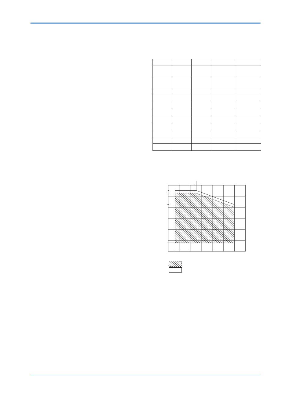
200
100
50
0
-50
-29
100
50
0
300
3URFHVV7HPSHUDWXUHÛ&
With Indicator
$PELHQW7HPSHUDWXUHÛ&
Without Indicator
85
-50
250
85
-29
80
80
F1301.ai
55
Figure 13.1
Ambient Temperature limit (Integal Type)