4 connection of dyc signal cable, Connection of dyc signal cable -5, Caution – Yokogawa digitalYEWFLO (DY) User Manual
Page 24
<4. WIRING>
4-5
IM 01F06A00-01EN
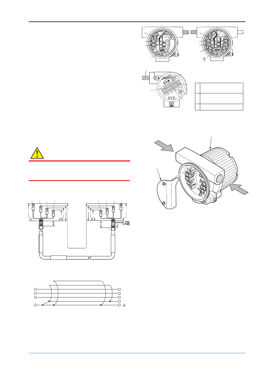
4.4 Connection of DYC Signal
Cable
The remote type signal cable is shown in Figure 4.3
and Figure 4.4, and the terminal is shown in Figure
4.5.
The maximum cable length is 30 m (97.5 feet).
Remove terminal box cover and wiring connection
dust-cap before wiring.
For remote type the converter has two electrical
connections (cable inlets). Use the left connection
as viewed from the terminal box for the DYC signal
cable and the right connection for the transmission
cable.
If a signal cable kit is supplied by YOKOGAWA,
both ends of the cable must be fi nished in
accordance with the following instructions. Refer to
Section 4.5 “End Processing Method of DYC Signal
Cable“.
CAUTION
After completing the signal cable connections,
install the shielded cover to signal cable terminal
as shown in Figure 4.6.
Unit : mm
F0403.ai
C
(Black)
B
(White)
A
(Red)
A
(Red)
B
(White)
C
(Black)
(Blue)
Specified
Length (L)
30m (max.)
DYC
Flowmeter
Converter
80
70
70
80
60
25
95
60
20
50
50
T
(Yellow)
T
(Yellow)
T: Only for / MV
Figure 4.3
DYC Signal Cable
A (Red)
T
(Yellow)
B (White)
C (Black)
(Red) A
(Yellow) T
(White) B
(Black) C
Outer shield
Inner shield
To Converter
To Flowmeter
F0404.ai
T
: Only for / MV
(Bule)
Figure 4.4
Construction of DYC Signal Cable
Detector (DY-N.../E1)
DYC
T
A
B
C
C
B
A
T
T
A
B
C
Flowmeter(DY-N)
Converter(DYA)
T: Only for /MV
F0405.ai
Input Terminal from built-
in temperature sensor
Input Terminals from
vortex detector
Common Terminal
T
A
B
C
Figure 4.5
Terminal of Detector and Converter
F0406.ai
Vortex Flow Converter
Shield Cover
Signal Cable(DYC)
Power Cable
Figure 4.6
Shielded Cover