2 model and suffix codes, 2 model, Suffi x codes -5 – Yokogawa digitalYEWFLO (DY) User Manual
Page 115: 2 model and suffi x codes, General specifications, Dya vortex flowmeter converter(remote type), Dyc signal cable
<13. GENERAL SPECIFICATIONS>
13-5
IM 01F06A00-01EN
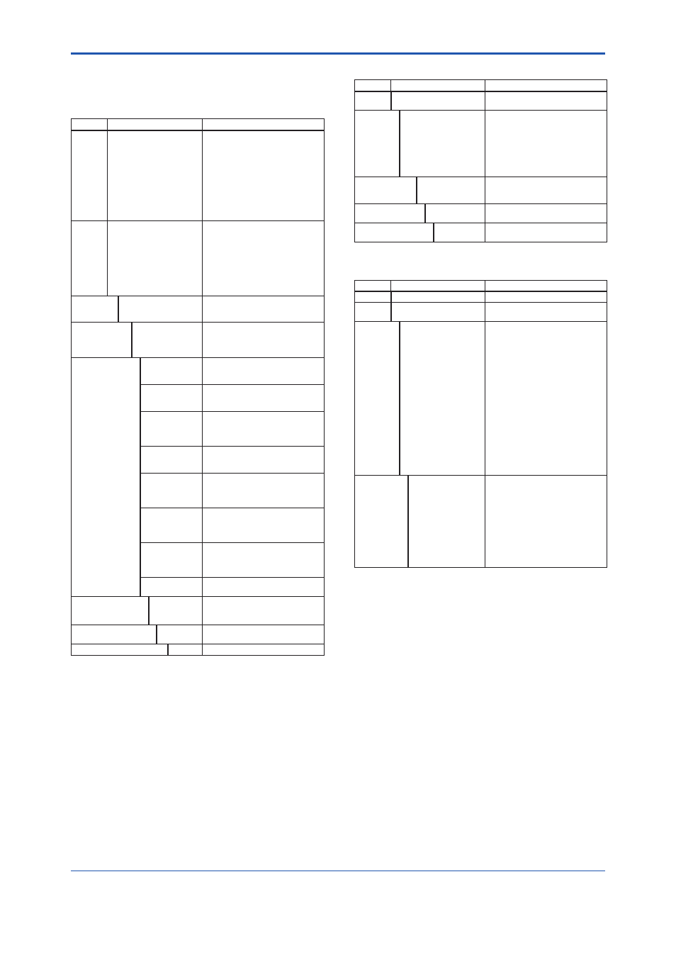
13.2 Model And Suffi x Codes
DY Vortex Flowmeter (Integral Type, Remote Type
detector)
Model
Suffi x Codes
Description
DY015
DY025
DY040
DY050
DY080
DY100
DY150
DY200
DY250
DY300
DY400
········································
········································
········································
········································
········································
········································
········································
········································
········································
········································
········································
Size 15 mm (1/2 inch)
Size 25 mm (1 inch)
Size 40 mm (1-1/2 inch)
Size 50 mm (2 inch)
Size 80 mm (3 inch)
Size 100 mm (4 inch)
Size 150 mm (6 inch)
Size 200 mm (8 inch)
Size 250 mm (10 inch)
Size 300 mm (12 inch)
Size 400 mm (16 inch)
Output
Signal
/Communication
-D ····································
-E·····································
-J ·····································
-F ·····································
-N ····································
4 to 20 mA DC, Pulse,
BRAIN Communication
4 to 20 mA DC, Pulse,
HART Communication *1
4 to 20 mA DC, Pulse,
HART 5/HART 7 Communication *2
Digital communication
(F
OUNDATION
Fieldbus protocol) *3
Remote type detector
Body
Material
*6, *7
A ································
B································
X································
JIS SCS14 A *4
ASTM CF8M *5
Others
Shedder bar
Material
*6, *7
L ··························
B··························
E··························
X··························
Duplex Stainless Steel
Stainless Steel
Duplex Stainless Steel (for TIIS Approval)
Others
Process
Connection
*8
RF: Raised Face
SF: Smooth Finish
RJ: Ring Joint
AJ1 ···················
AJ2 ···················
AJ4 ···················
JIS 10 K Wafer
JIS 20 K Wafer
JIS 40 K Wafer
AA1 ···················
AA2 ···················
AA4 ···················
ANSI Class 150 Wafer
ANSI Class 300 Wafer
ANSI Class 600 Wafer
AD1 ···················
AD2 ···················
AD3 ···················
AD4 ···················
DIN PN10 Wafer
DIN PN16 Wafer
DIN PN25 Wafer
DIN PN40 Wafer
BJ1 ···················
BJ2 ···················
BJ4 ···················
JIS 10K Flange(RF)
JIS 20K Flange(RF)
JIS 40K Flange(RF)
BA1 ···················
BA2 ···················
BA4 ···················
BA5 ···················
ANSI Class 150 Flange(RF)
ANSI Class 300 Flange(RF)
ANSI Class 600 Flange(RF)
ANSI Class 900 Flange(RF)
BS1 ···················
BS2 ···················
BS4 ···················
BS5 ···················
ANSI Class 150 Flange(RF, SF)
ANSI Class 300 Flange(RF, SF)
ANSI Class 600 Flange(RF, SF)
ANSI Class 900 Flange(RF, SF)
BD1 ···················
BD2 ···················
BD3 ···················
BD4 ···················
DIN PN10 Flange(RF)
DIN PN16 Flange(RF)
DIN PN25 Flange(RF)
DIN PN40 Flange(RF)
CA4 ···················
CA5 ···················
ANSI Class 600 Flange(RJ)
ANSI Class 900 Flange(RJ)
Electrical
Connection *9
-0 ··················
-2 ··················
-4 ··················
JIS G 1/2 Female
ANSI 1/2 NPT Female *10
ISO M201.5 Female
Indicator
*11
D ··············
N ··············
With Indicator
None Indicator, Remote type detector
Options
/
Refer to Option Specifi cations
DYA Vortex Flowmeter Converter(Remote Type)
Model
Suffi x Codes
Description
DYA
········································
Vortex Flowmeter Converter
(Remote Type)
Output
Signal
/Communication
-D ·······························
-E································
-J ································
-F ································
4 to 20 mA DC, Pulse
BRAIN Communication
4 to 20 mA DC, Pulse
HART Communication *1
4 to 20 mA DC, Pulse
HART 5/HART 7 Communication *2
Digital communication
(FOUNDATION Fieldbus protocol) *3
Electrical
Connection *9
0 ··························
2 ··························
4 ··························
JIS G 1/2 Female
ANSI 1/2 NPT Female *10
ISO M20 ×1.5 Female
Indicator
D ·····················
N ·····················
With Indicator
None Indicator
Options
/
/MV
Refer to Option Specifi cations
Multi-Variable Type *12
DYC Signal Cable
Model
Suffi x Codes
Description
DYC
········································ Signal Cable
Cable
End
-0 ·····································
-1 ·····································
Without End fi nish *13
With End fi nish
Cable
Length
*14
-05 ······························
-10 ······························
-15 ······························
-20 ······························
-25 ······························
-30 ······························
-35 ······························
-40 ······························
-45 ······························
-50 ······························
-55 ······························
-60 ······························
-65 ······························
-70 ······························
-75 ······························
-80 ······························
-85 ······························
-90 ······························
-95 ······························
5 m
10 m
15 m
20 m
25 m
30 m
35 m
40 m
45 m
50 m
55 m
60 m
65 m
70 m
75 m
80 m
85 m
90 m
95 m
Options
/C1 ··························
/C2 ··························
/C3 ··························
/C4 ··························
/C5 ··························
/C6 ··························
/C7 ··························
/C8 ··························
/C9 ··························
/MV ·························
Cable End Finish Parts
1 set
2 set
3 set
4 set
5 set
6 set
7 set
8 set
9 set
Multi-Variable Type
*1: Output signal code ‘-E’: HART 5. (Output signal code ‘-J’ is recommended for HART communication.)
*2: Output signal code ‘-J’: HART 5 or HART 7 selectable. Specify HART 5 or HART 7 when ordering.
*3: For FOUNDATION Fieldbus protcol, refer to GS 01F06F01-01EN. For Fieldbus communication type, there are not setting keys on the display board.
*4: In case of A (JIS SCS14A), the process connection is available for JIS (AJ, BJ)
*5: In case of B (ASTM CF8M), the process connection is available for ANSI (AA, BA, BS, CA) and DIN (AD, BD).
*6: Refer to Table 13.1.
*7: Users must consider the characteristics of selected wetted parts material and the infl uence of process fl uids. The use of inappropriate materials can result in the leakage of
corrosive process fl uids and cause injury to personnel and/or damage to plant facilities. It is also possible that the instrument itself can be damaged and that fragments from
the instrument can contaminate the user's process fl uids.
Be very careful with highly corrosive process fl uids such as hydrochloric acid, sulfuric acid, hydrogen sulfi de, sodium hypochlorite, and hightemperature steam (+150°C
[+302°F] or above). Contact Yokogawa for detailed information of the wetted parts material.
*8: Refer to Table 13.2.
*9: In case of an explosion protect type, it depends for an electrical connecion on the kind of an explosion protect type. Refer to Section 13.6 “Option Specifi cations (For Explosion
Protected Type)”.
*10: In case of /FF1 or /CF1, CF11, /KF2, /SF2, the screw length is deeper than ANSI standard for 0.5 to 2 threads.
*11: Indicator is not available for remote type detector.
*12: DYA-/MV and DY-N***/MV should be combined.
*13: One set of end fi nish part is attached.
*14: DYC Signal Cable can be used up to 30m. When you divide the cable below 30m, select the Cable End code [-0].