Yokogawa digitalYEWFLO (DY) User Manual
Page 112
<13. GENERAL SPECIFICATIONS>
13-2
IM 01F06A00-01EN
Weight:
Refer to Section 13.7 “External Dimensions”.
Mounting:
Integral type and Remote type detector:
Flange mounting or wafer mounting by
fl ange adjacent to the pipeline.
Remote type converter: 2 inch pipe mounting.
Electrical Specifi cations
Note*: Pulse output,alarm output and status output use the
common terminal, therefore these functions are not
used simultaneously.
Output Signal (): Dual Output (Both Analog
and Transistor contact output can be obtained
simultaneously). In this ca
se refer to Section
3.2 “Piping Precautions” for power supply
and pulse output wiring.
Analog: 4 to 20 mA DC, 2-wire system.
Transistor Contact Output*:
Open collector, 3-wire system.
Pulse,alarm,status output are selected by
parameter setting.
Contact rating: 10.5 to 30 V DC, 120 mA DC
Low level: 0 to 2 V DC. (refer to Figure 13.3)
Communication Requirements:
Communication Signal:
BRAIN or HART communication signal
(superimposed on a 4 to 20 mA DC signal)
Note: HART is a registered trademark of the HART
Communication Foundation.
Conditions of Communication Line:
Load Resistance:
250 to 600
Ω(including cable resistance).
Refer to Figure 13.2.
Supply Voltage:
16.4 to 42 V DC for digital communications
BRAIN and HART protocols. (16.4 to 30 V DC
for intrinsically safe type).
Refer to Figure 13.2.
BRAIN:
Space from other Power Line: 15cm or more
(Parallel wiring should be avoided.)
Communication Distance:
Up to 2 km,when polyethylene insulated
PVC-sheathed cables (CEV cables) are used.
Communication distance varies depending on
type of cable used and wiring.
Load Capacitance: 0.22
μF or less
Load Inductance: 3.3 mH or less
Input Impedance Communicating Device:
10 k
Ω or more at 2.4 kHz.
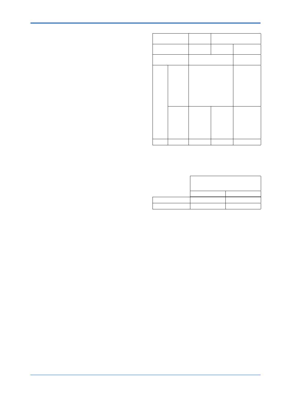
Selection of HART 5/ HART 7
Output Signal
Code
-E
-J
Ordering
Information
—
Specify “5”
Specify “7”
HART Protocol
Revision
HART 5
HART 7
Selection
guide
Requirement
for HART 7
functionarlity
NO
YES
Be sure to
confi rm the
protocol
revision
of the HART
confi guration
tool
shown in *2.
Other
conditions
Not
available
to switch to
HART 7
protocol
after
delivery.
Available to
switch to HART
7 protocol after
delivery by
userconfi guration.
—
Remarks
*1
*2
*2
*1: “-E” is HART5 exclusive model and will be terminated. “-J”
is recommended for HART communication.
*2: HART protocol revision for the device and HART
confi guration tool HART7 communication is supported
by FieldMate R2.02 or later.
HART protocol revision and availability
Protocol revision
supported by HART
confi guration tool
5
7
DY or DYA HART 5
Available
Available
DY or DYA HART 7
Not Available
Available
Note: Protocol revision supported by HART confi guration tool must
be the same or higher than that of the digitalYEWFLO.
Functions:
Damping Time Constant:
0 to 99 Sec (63% response time)
Note: Delay time is 0.5 Sec.
Analog output circuit time constant is 0.3 Sec.
Pulse Output Function*:
Pulse output is selected from scaled pulse,
unscaled pulse, frequency (number of pulses
output per second at 100% of output).
Pulse frequency: Max 10 kHz
Duty cycles: Approx.50% (1:2 to 2:1)
Self-diagnostics and Alarm Output *:
In case alarm (over range output signal,
EEPROM error, vibration noise, abnormal fl ow
such as clogging, bubble) occurs, an alarm
signal is output and indicated.
The alarm signal output goes from close(ON) to
open(OFF) during alarming.
Analog Output Function:
Analog output is selected from fl owrate and
temperature value when option code /MV is
selected.