2 setting parameters required for operation – IAI America ACON-PO User Manual
Page 50
40
4. Operation Using I/O Signals
4.2.2
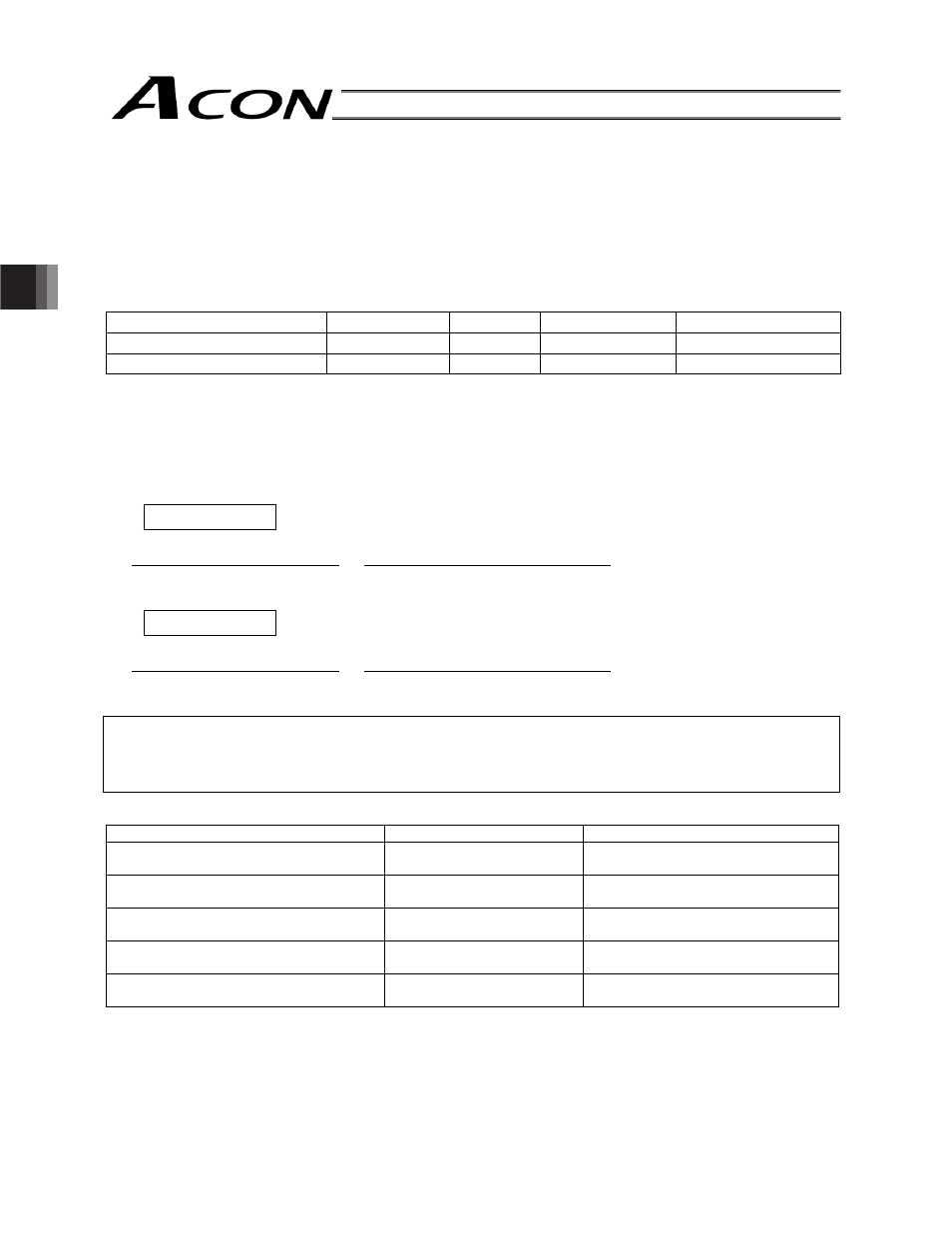
Setting Parameters Required for Operation
The following parameters must always be set prior to every operation.
(These parameters are all you need to set to perform operations that only involve positioning.)
(1) Electronic gear
User Parameter Nos. 65 and 66 (Electronic gear numerator and denominator)
Name
Symbol
Unit
Input range
Default (reference)
Electronic gear numerator
CNUM
-
1 ~ 4096
200
Electronic gear denominator
CDEN
-
1 ~ 4096
15
These parameters are used to determine the unit travel distance of the actuator per one pulse in input command
pulse train.
Unit travel distance of linear-motion axis = Minimum travel unit (1, 0.1, 0.01 mm, etc.)/pulse
Unit travel distance of rotational axis = Minimum travel unit (1, 0.1, 0.01 deg, etc.)/pulse
Calculation Formula for Electronic Gear
Linear-motion axis
Electronic gear numerator (CNUM)
Encoder pulses (pulses/rev)
Electronic gear denominator
(CDEN)
=
Ball screw lead length (mm/rev)
x Unit travel distance (mm/pulse)
Rotational axis
Electronic gear numerator (CNUM)
Encoder pulses (pulses/rev)
Electronic gear denominator
(CDEN)
=
360 (deg/rev) x Gear ratio of rotational axis
x Unit travel distance (deg/pulse)
Reference
The actuator speed is calculated as follows:
Speed = Unit travel distance x Input pulse frequency (Hz)
Take note that if the unit travel distance is too small, the actuator may not be able to reach the maximum speed.
List of encoder pulses and leads length by model
Actuator type
Encoder resolution
Lead length
RCA or RCA2 other than RCA2-
N
800
(Pulse/rev)
Check the lead marking on the side
panel of the controller.
RCA2-
N
1048
(Pulse/rev)
Check the lead marking on the side
panel of the controller.
RCL-SA1L/SA4L/SM4L/RA1L
715
(Pulse/rev)
30.03 mm
RCL-SA2L/SA5L/SM5L/RA2L
855
(Pulse/rev)
35.91 mm
RCL-SA3L/SA6L/SM6L/RA3L
1145
(Pulse/rev)
48.09 mm