8 wiring the emergency stop circuit, 1 cutting off the drive signal (standard) – IAI America ACON-PO User Manual
Page 34
24
3. Installation and W
iring
3.8
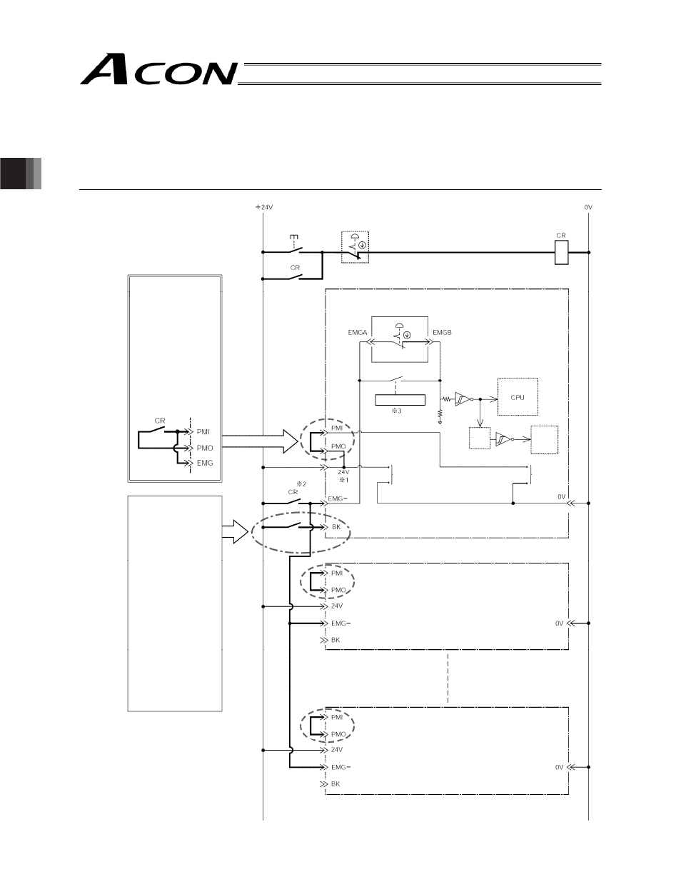
Wiring the Emergency Stop Circuit
3.8.1
Cutting Off the Drive Signal (Standard)
Shown below is an example when the emergency stop circuit of the entire system is used to actuate an emergency
stop on multiple controllers.
However, the emergency stop switch on the teaching pendant cannot actuate an emergency stop of the entire system.
External EMG
switch
EMG signal
detection (H)
Time
constant
Drive stop
signal (L) Motor
drive
circuit
External EMG circuit
Motor power
supply
Normally these
terminals are
connected by jumper
wires. If the
applicable safety
category requires
cutoff of the motor
drive source, use the
following circuit.
(The motor drive
source will be cut off
at the same time the
EMG switch is
operated.)
The brake is turned
on/off automatically
based on servo
on/off actions.
To release the
brake manually,
close the brake
release switch. The
brake will be
released.
* The user must
provide the brake
release switch.
(Switch)
24 VDC
Contact capacity
0.2 A or more
EMG switch of
teaching pendant
Connection
detection circuit
Controller power
supply
Brake release
switch
2nd controller
nth controller