6 wiring the power supply, 7 wiring the brake forced-release switch – IAI America ACON-PO User Manual
Page 33
23
3. Installation and W
iring
Push with a flat-head
screwdriver to open the cable
inlet.
Input power supply
24 VDC
Power-supply
terminal block
Cable inlet
Brake forced-release
switch
Input power supply
24 VDC
Power-supply
terminal block
3.6
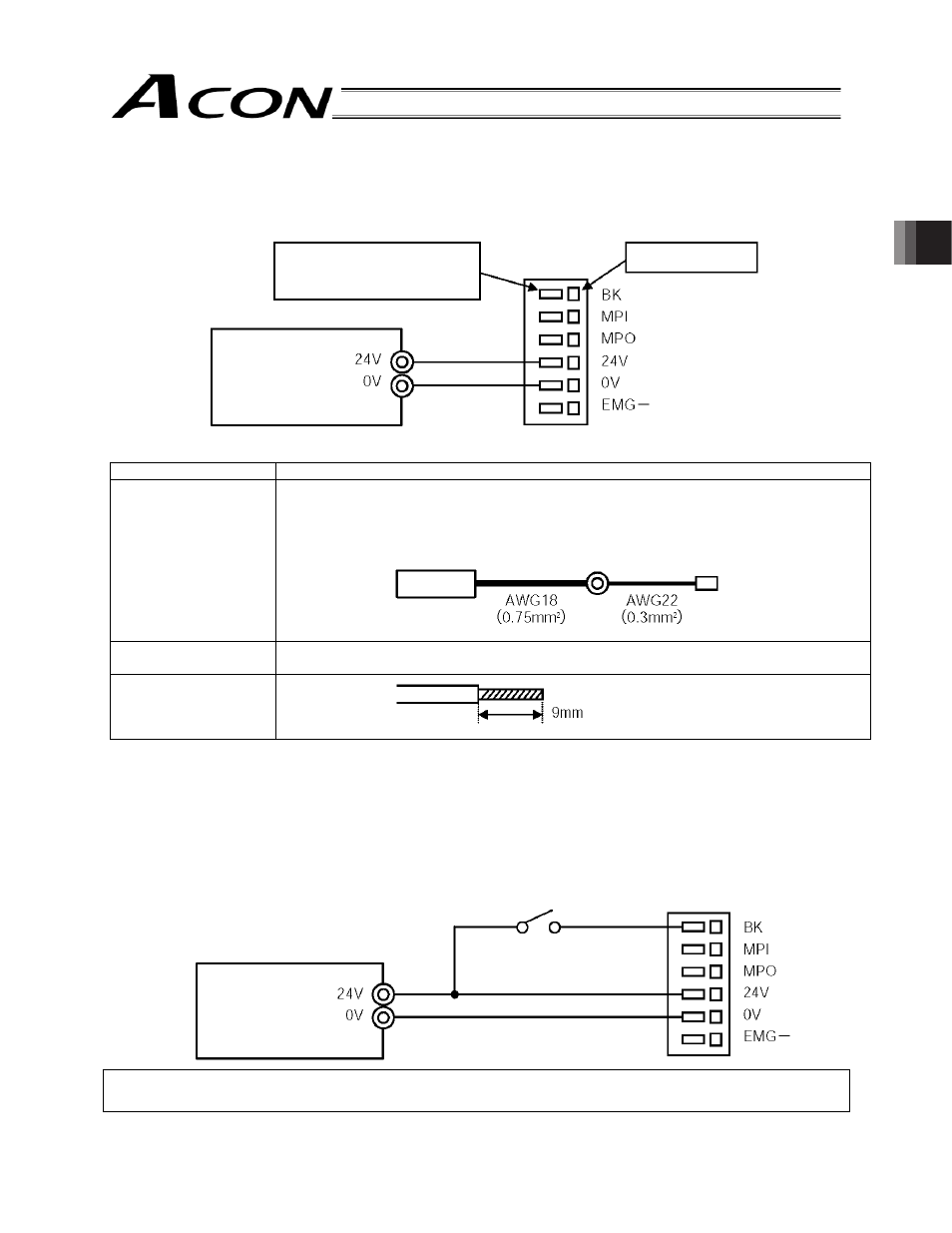
Wiring the Power Supply
Connect the positive side and negative side of the 24-VDC power supply to the 24-V terminal and 0-V terminal on the
power-supply terminal block, respectively.
Use a wire satisfying the following specifications.
Item Specification
Applicable wire
Twisted wire: AWG 22 (0.3 mm
2
) (copper wire)
(Note) Provide proper termination to prevent shorting due to contact with wire offcut.
If the wiring path is long, provide a relay terminal block and connect the original wire to
another wire of a different size.
Temperature rating of
insulation sheath
60
qC or above
Length of bare wire
3.7
Wiring the Brake Forced-release Switch
If the actuator is equipped with a brake, provide a forced-release switch to permit a reset means during startup
adjustment or in case of emergency.
The customer must provide the switch (24 VDC, with a minimum contact capacity of 0.2 A).
Connect one side of the switch to the positive side of the 24-VDC power supply, and connect the other side to the BK
terminal on the power-supply terminal block.
The brake will be released when the switch is closed.
Danger: If the actuator is oriented vertically, exercise due caution when releasing the brake to prevent the slider/rod
from dropping unexpectedly to pinch your hand or damage the robot hand or work.
Input power
supply
Relay terminal block Power-supply terminal block