3 command pulse train input specifications – IAI America ACON-PO User Manual
Page 43
33
4. Operation Using I/O Signals
ACON-PL
11/PP
12 PP
13/NP
14 NP
Mounting plate
FG
ACON-PO
DC 24 V
r 10%
Mounting plate
1 24
V
2 0
V
11 /pp
12 ---
13 /NP
14
---
FG
Positioning unit
Positioning unit
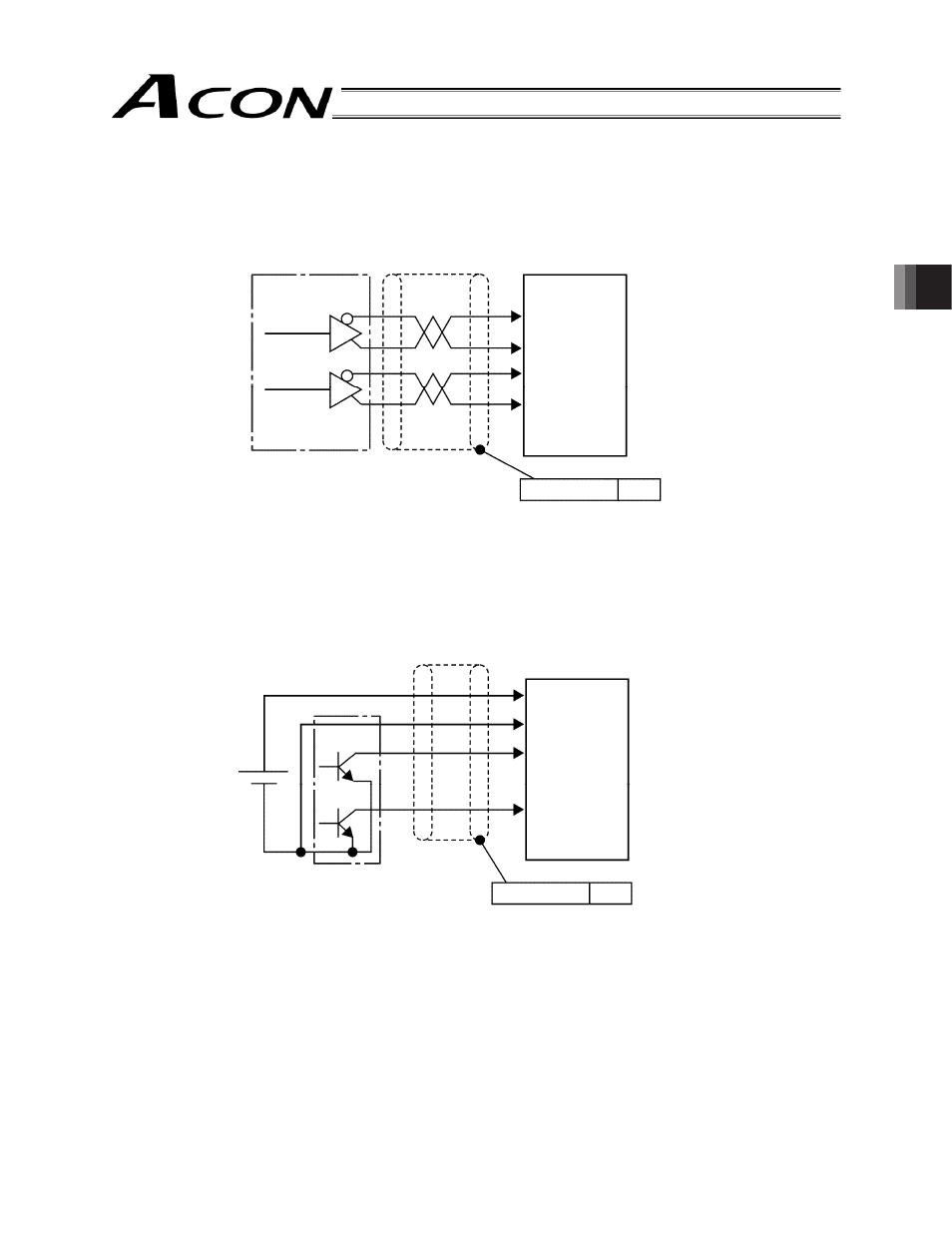
4.1.3
Command Pulse Train Input Specifications
[Input using a differential line driver]
Applicable line driver: 26C31 or equivalent
Note: Always connect the shield of the twisted pair cable joined to the connector, to the mounting plate.
[Input using an open collector]
Note 1: Always connect the shield of the twisted pair cable joined to the connector, to the mounting plate.
Note 2: Some open collector outputs have a built-in pull-up resistor. In this case, remove the pull-up resistor.
This manual is related to the following products: