26 3. installation and w iring – IAI America ACON-PO User Manual
Page 36
26
3. Installation and W
iring
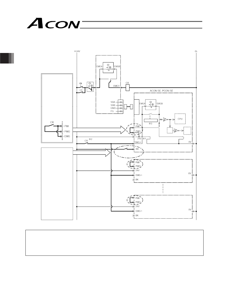
To actuate an emergency stop on the entire system using the emergency stop switch on the teaching pendant, use a
SIO converter.
You can also reflect the operation of the teaching pendant’s emergency stop switch when a gateway unit is used.
Notes on power supply and emergency stop circuit
*1 Refer to the specification list for the load current of one controller.
*2 The input current at the EMG- terminal of each controller is 5 mA. If the relay contact CR is to be connected to
the EMG- terminals of multiple controllers, check the contact capacity of the relay.
*3 When the teaching pendant is plugged into the controller, the controller automatically recognizes the
connection.
SIO
connector
EMG signal
detection (H)
Time
constant
Drive stop
signal (L) Motor
drive
circuit
SIO converter
External
EMG
reset
switch
External
EMG
circuit
Normally these
terminals are
connected by jumper
wires. If the
applicable safety
category requires
cutoff of the motor
drive source, use the
following circuit.
(The motor drive
source will be cut off
at the same time the
EMG switch is
operated.)
The brake is turned
on/off automatically
based on servo
on/off actions.
To release the
brake manually,
close the brake
release switch. The
brake will be
released.
* The user must
provide the brake
release switch.
(Switch)
24 VDC
Contact capacity
0.2 A or more
EMG switch of
teaching pendant
Connection
detection circuit
Controller power supply
2nd controller
nth controller
EMG switch of
teaching pendant
Brake release
switch
Port switch
SIO
communication
Motor power
supply