Specifications, 1 basic specifications, 16 6shfl¿fdwlrqv – IAI America ACON-PO User Manual
Page 26
16
6SHFL¿FDWLRQV
2. Specifications
2.1 Basic
Specifications
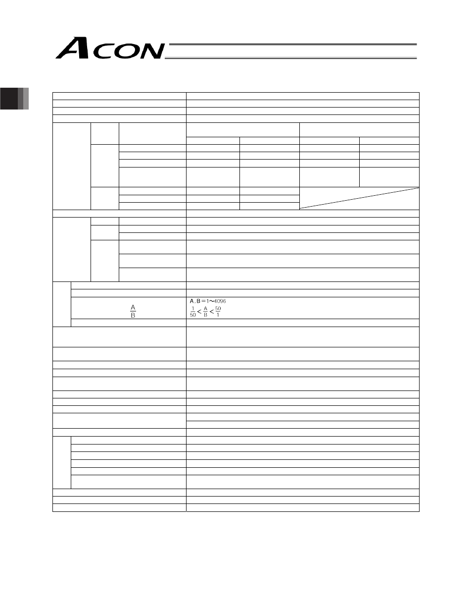
Specification item
Description
Model ACON-PL/PO
Number of controlled axes
1 axis per unit
Power-supply voltage
24 VDC
r 10%
Standard specification/Support high
acceleration/deceleration
Support power-saving
Actuator Motor
type
Rated [A]
Maximum (Note 2)
Rated [A]
Maximum (Note 2)
10 W
1.3
4.4 1.3 2.5
20 W [Model code: 20]
1.3
4.4
1.3
2.5
30 W
1.3
4.0 1.3 2.2
RCA/
RCA2
20 W [Model code: 20S]
For RA3, RA4 and TA5
types only
1.7
5.1 1.7 3.4
2 W
0.8
4.6
5 W
1.0
6.4
Motor power
supply
capacity
(Note 1)
RCL
10 W
1.3
6.4
Heat output
8.4 W
RCA, 800
Pulse/rev
RCA2-
N
1048 Pulse/rev
RCA2
Other than RCA2-
N
800 Pulse/rev
RA1L/ SA1L/
SA4L/SM4L
715 Pulse/rev
RA2L/ SA2L/ SA5L/
SM5L
855 Pulse/rev
Encoder
resolution
RCL
RA3L/ SA3L/ SA6L/
SM6L
1145 Pulse/rev
Control mode
Position control by pulse train input
Maximum input pulse frequency
60 kpps max. (open collector) / 200 kpps max. (differential)
Command pulse multiplier
(Electronic gear:
)
F
unct
io
n/
per
form
an
ce
Positioning complete band
0.1 mm ~ 999.999 mm (set by parameters)
Power supply for I/O signal I/F
24 VDC
r 10%
Some open collectors have outputs that come with a built-in pull-up resistor. If any such
open collector is used, remove the pull-up resistors or use ports without pull-up resistor.
Backup memory
Parameters are saved in a non-volatile memory; serial EEPROM; rewritable approx.
100,000 times
PIO interface
24 VDC, insulated; dedicated input/output
PIO interface power supply
24 VDC
r 10% (supplied externally)
LED indicator
SV (green) --- Whether or not the servo is on / ALM (red) --- Whether or not an alarm is
present or emergency stop is actuated.
Serial communication
RS485, 1 channel (for teaching pendant/dedicated PC software)
Encoder interface
Incremental specification conforming to EIA RS-422A/423A
Forced release of electromagnetic brake
24 V is applied to the BK terminal on the power-supply terminal block.
Actuator cable: 20 m or shorter
Cable length
I/O shield cable: 2 m or shorter (open collector) or 10 m or shorter (differential)
Dielectric strength
500 VDC 10 m
:
Surrounding air temperature
0 to 40
qC
Surrounding humidity
85% RH or below (non-condensing)
Surrounding environment
Free from corrosive gases.
Ambient storage temperature
-10 to 65
qC
Ambient storage humidity
90% RH or below (non-condensing)
E
nvir
onm
ent
Vibration resistance
10 to 57 Hz in all X/Y/Z directions / Single amplitude: 0.035 mm (continuous), 0.075 mm
(intermittent)
Protection class
Natural air cooling (IP20)
Weight
128 g or below
External dimensions
35 (W) x 120 (H) x 68 (D) mm
(Note 1) Rush current of 5 to 12 times the rated current is conducted for approximately 1 to 2 msec after turning the power on.
Note that the rush current value varies depending on the impedance of the power line.
(Note 2) The maximum current is conducted at the servo motor exciting phase detection performed in the first servo on
processing after turning the power on (normally: approximately 1 to 2 seconds, maximum: 10 seconds)
* For the DC power supply of +24 V, select the “peak load” specification or a power supply having sufficient allowance. In particular,
pay attention when the robot has a remote sensing function.
(set by parameters)