3 noise elimination measures and grounding – IAI America ACON-PO User Manual
Page 30
20
3. Installation and W
iring
3.3
Noise Elimination Measures and Grounding
The following explains the noise elimination measures that should be taken when using this controller.
(1) Wiring and power supply connection
[2]
Precautions regarding wiring method
(2) Noise sources and elimination
AC solenoid valves, magnet switches, relays
Surge absorber
Connect to each coil over the shortest possible wiring distance.
When a surge absorber is installed on the terminal block, etc., its noise
elimination effect will decrease if the distance from the coil is long.
Controller
Other
equipment
Controller
Other
equipment
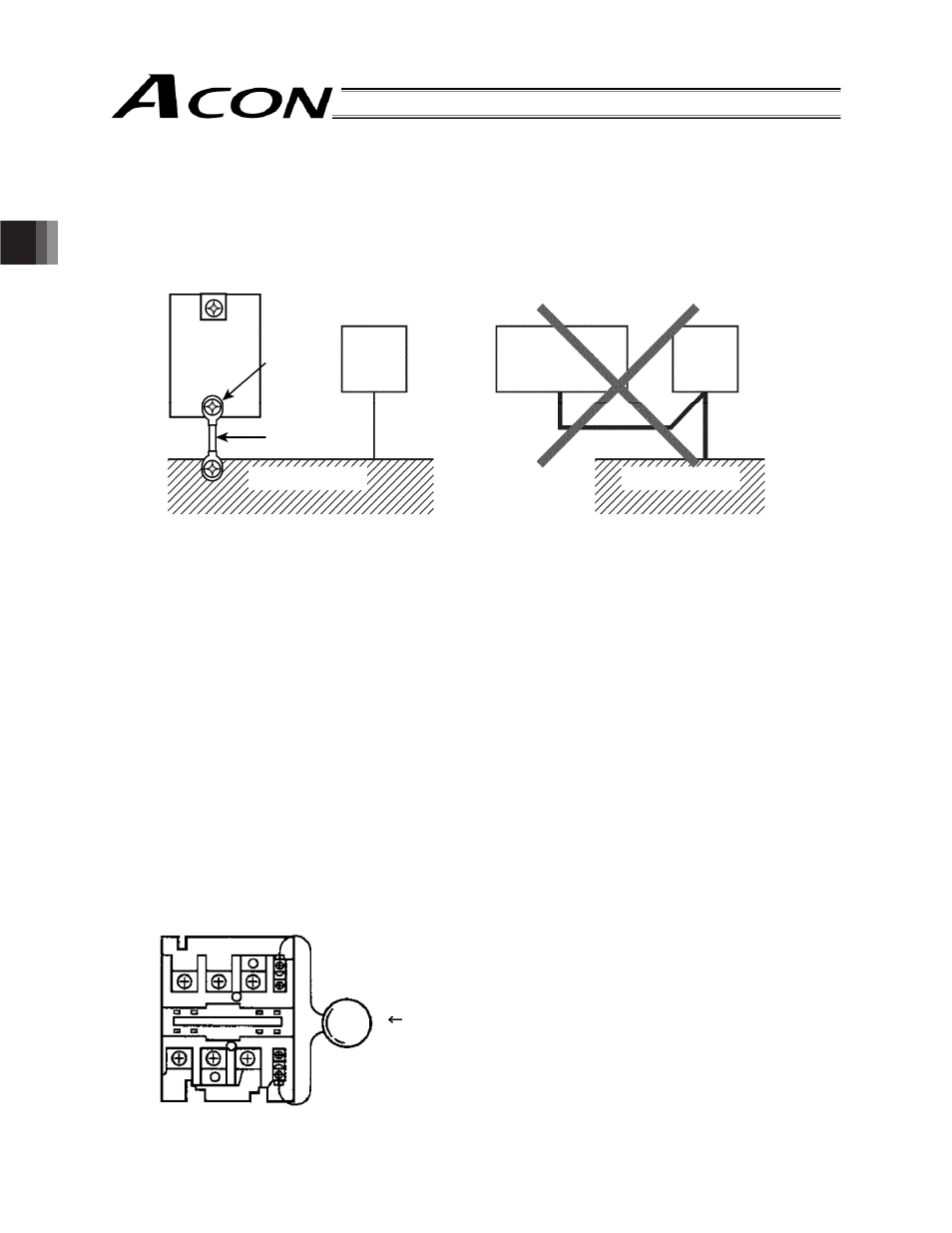
Ground terminal
Use the thickest
possible line and
wire it over the
shortest distance.
Connect the
ground line to
the mounting
screw of the
main unit.
Ground terminal
Ground resistance of 100
7 or less
Do not link or connect the ground line
with other devices; ground it for each
controller.
[1]
Grounding must be made by ground resistance of 100
7
Moreover, the thickness of cable shall be 1.6 mm or thicker.
Measure: Install a surge absorber in parallel with the coil
Use a twisted cable to connection the 24 VDC external power supply.
Separate wiring of signal lines and encoders from power supply lines and power lines.
(Do not tie them together or place in the same cable duct.)
If you want to extend the motor or encoder cable bey ond the length of the supplied cable, contact IAI.
Noise generates from many sources, but the most comm on sources of noise you should consider when designing
a system are solenoid valves, magnet switches and relays.
Noise from these sources can be eliminated by implementing the measures specified below.