5 external connection diagram, 22 3. installation and w iring – IAI America ACON-PO User Manual
Page 32
22
3. Installation and W
iring
3.5
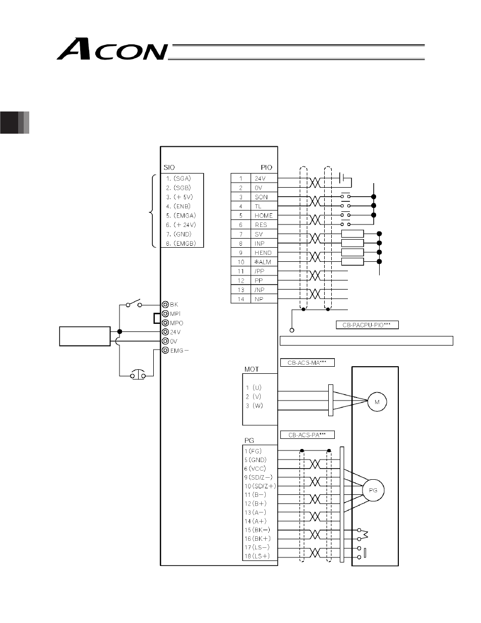
External Connection Diagram
An example of standard wiring is shown below.
The wire colors of the robot encoder relay cable are different from those of the standard encoder relay cable. Refer to
3.9.2, “Encoder Relay Cable.”
Black
White/Black
Red
White/Red
Green
White/Green
Yellow
White/Yellow
Brown
White/Brown
Blue
White/Blue
Gray
White/Gray
Red
White
Black
Drain
Black
Red
Green
Orange
White/Black
White/Red
White/Yellow
White/Blue
Blue
Yellow
White/Gray
White/Purple
For teaching pendant/
PC connection
Brake release
switch
ACON-PL controller
External EMG
switch
Input power
supply
24 VDC
Terminal block
24-VDC power supply
for I/O signals
0 V (NPN specification)
24 V (PNP specification)
24 V (NPN specification)
0 V (PNP specification)
Load
Motor relay cable
Actuator
Motor
Encoder relay cable
Encoder
Holding
brake
I/O shield cable
Load
Load
Load
* Affix the round terminal onto the enclosure using a mounting screw.
Home
check
sensor
24 V
0 V