37 4. w iring diagram, Robot end controller end – IAI America IX-NNW3515H User Manual
Page 43
37
4. W
iring Diagram
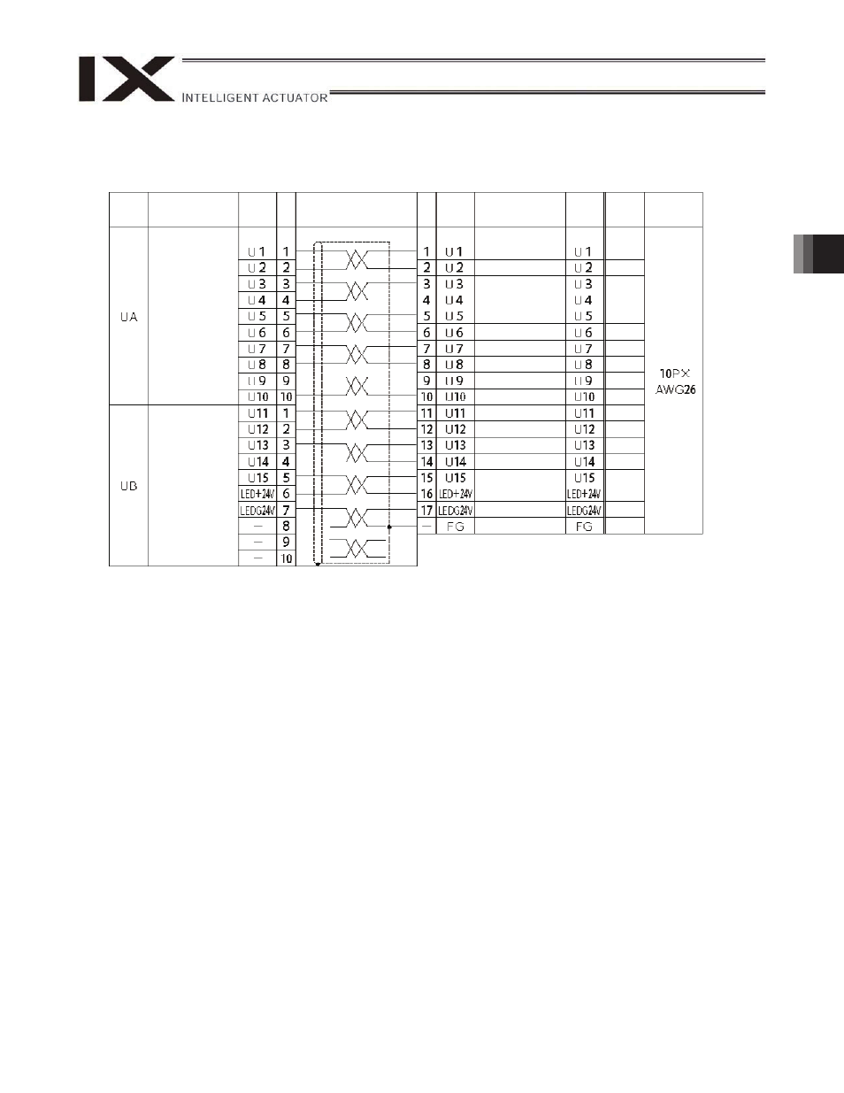
(3) UA and UB cables (outside robot)
DWG No. 1068765*
Robot end
Controller end
Orange 1
red
Orange 1
black
Light gray
1 red
Light gray
1 black
White 1
red
White 1
black
Yellow 1
red
Yellow 1
black
Pink 1 red
Pink 1
black
Orange 2
red
Orange 2
black
Light gray
2 red
Light gray
2 black
White 2
red
White 2
black
Yellow 2
red
Green
Tube
symbol
Connector
Signal Pin
No.
Connection
ID No.
Cable
Pin
No.
Connector
Signal
Tube
symbol
Double-brazed
crimp socket
DF11-10DS-2C
(by Hirose
Electric)
Same as above
Un-isolated
terminal (Y type)
F0.3-3
Same as above
Same as above
Same as above
Same as above
Same as above
Same as above
Same as above
Same as above
Same as above
Same as above
Same as above
Same as above
Same as above
Same as above
Same as above
Same as above
Same as above