IAI America IX-NNW3515H User Manual
Page 24
18
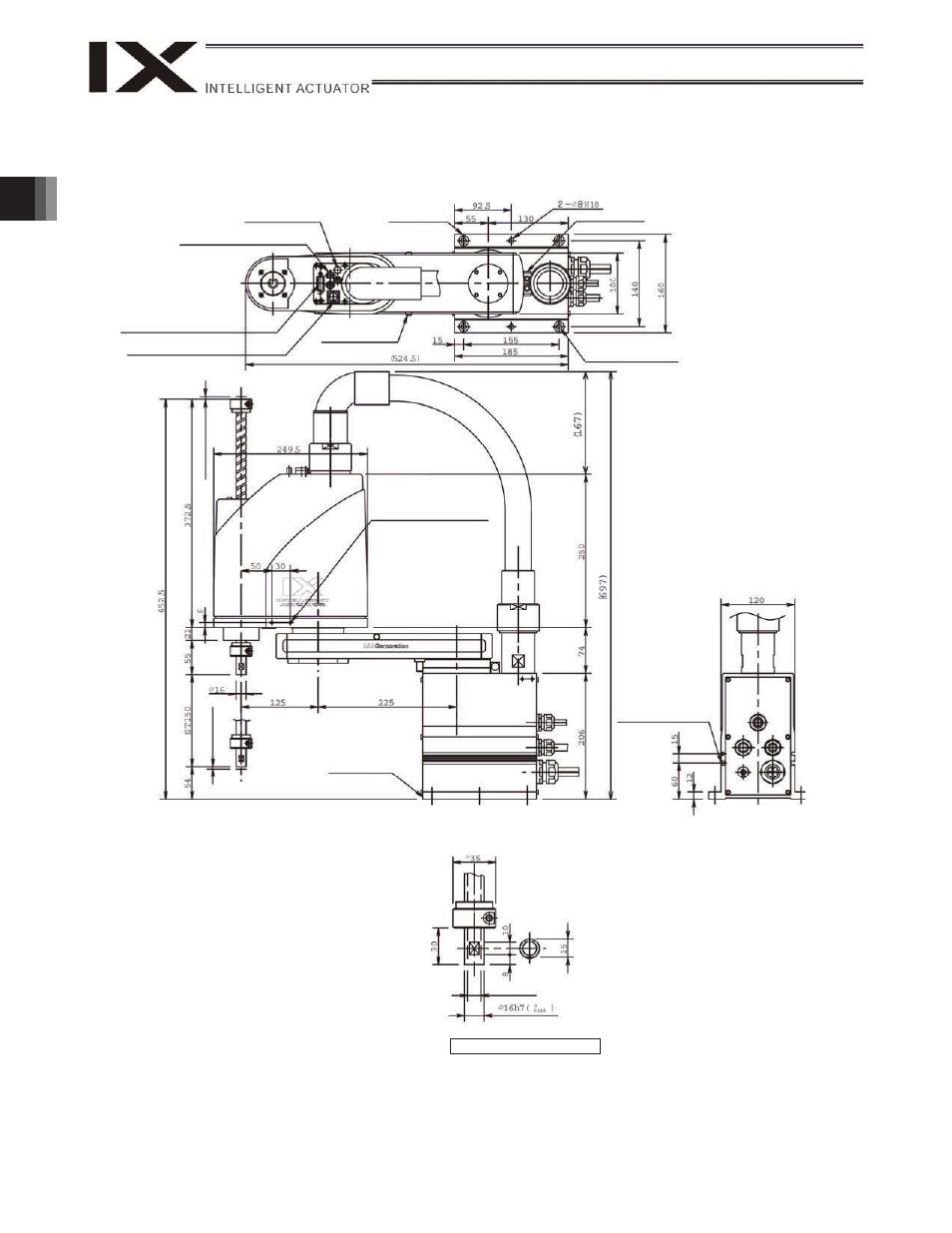
2. External Dimensions
IX-NNN3515H (Arm Length 350, Standard Specification)
ALM (indicator)
4 quick air-tube joint
(black, red, white; 3 locations)
User connector
(D-sub 15-pin connector)
BK SW
(Brake-release switch)
Arm 2 stopper
Reference surface
Arm 1 stopper
4-
9
16, counterbore depth 0.5
4 (
M
echa
ni
cal
e
nd)
4 (
M
echa
ni
cal
e
nd)
Tapped hole for peripheral
installation (4-M4, depth 12)
Same on opposite surface
T-slot for peripheral
installation (M3, M4)
11 (inner diameter)
Detailed view of arm end
*1: External force applied to the spacers must not
exceed 30 N in the axial direction or 2 N
m in the
rotating direction (for each spacer).
*2: The LED operates only when the user provides a
circuit that receives controller I/O output signal and
supplies 24 VDC to the LED terminal in the user
connector.
Reference surface