Name of each part, 1 robot – IAI America IX-NNW3515H User Manual
Page 18
12
1. Name of Each Part
1. Name of Each Part
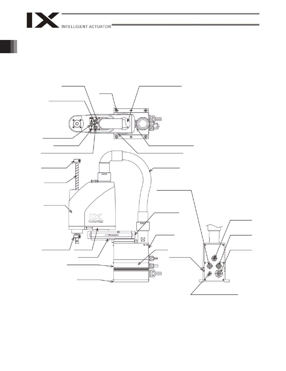
1.1 Robot
IX-NNN2515H/3515H
ALM (indicator)
4 user piping
(black, red, white;
3 locations)
Reference
surface
Top cover (arm 1)
Mechanical stopper for arm 1
Mechanical stopper for arm 2
BK SW (Brake- release switch)
User connector
Ball screw
spline shaft
Cover (arm 2)
Mechanical
stopper for axis
3 (vertical axis)
Wiring duct
End cover (arm 1)
Arm 2
Arm 1
Front panel (base)
Reference
surface
Base
Rear panel
(base)
M cable (outside robot)
T-slot for peripheral
installation
(M3, M4)
Air tubes
(
4: 3 pcs.)
U cable
(outside robot)
PG cable
(outside robot)
BK power cable
(outside robot)
Mechanical
stopper for axis
3 (vertical axis)
Spacer for user
part installation
This manual is related to the following products: