IAI America IX-NNW3515H User Manual
Page 33
27
4. W
iring Diagram
26
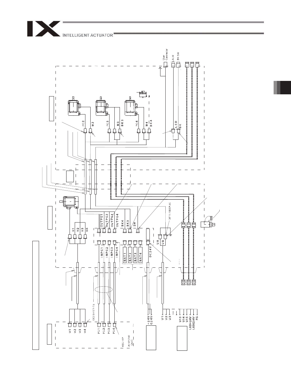
Wiring/Piping Diagram (Arm Length: 250/350)
Notes
(1)
The actual la
y
out
of board conn
ectors varies from t
h
is draw
ing.
(2)
Since the brake
po
w
e
r circuit is provided on the p
rimary
side (high-voltage side)
, a dedicated 24 V po
w
e
r suppl
y
is req
uire
d for this circuit.
The 24 V po
wer
supply
f
or I/
O circuits used on the
secondary
side (low
-voltage side) cannot be share
d.
(3)
To operate the al
arm LED, the
user must provide
a circuit that uses the
controller I/
O output signal.
(4)
The user connec
tor is w
at
erp
roof.
(5)
FG is connected
to pin 16 of the c
onnector.
IX-NNW2515H/3515H
Controller
Inside
base
F
lex
ibl
e
cable
Inside arm 2
Brake po
w
e
r
terminals
User w
iring
terminals
C
abl
e
fi
x
cap (
C
apc
on)
M
cable (
o
utside
r
obo
t)
D
W
G
No.
10
687
63*
Socket
172
159-
1
(T
y
c
o Electr
onics
AM
P
)
S
e
rv
o
m
o
to
r
fo
r
a
x
is 1
(a
rm
1
)
D
W
G
No.
10
687
95*
PG ca
ble (
inside
r
obo
t)
M ca
b
le
(in
side
ro
bo
t)
U cable (
insid
e
r
o
b
o
t)
Socket
DF11-8DS-2C (Hirose)
S
e
rv
o
m
o
to
r
fo
r
a
x
is 2
(a
rm
2
)
Socket
172
159-
1
(
T
y
c
o
Electronics AMP)
S
e
rvo
m
o
to
r w
it
h
br
ake
for
ax
is
3
(Z-axis)
Socket
172
157-
1
(
T
y
c
o
Electronics AMP)
S
e
rv
o
m
o
to
r
fo
r
ax
is 4 (R-axis)
Electr
om
ag
netic
br
ake
for
ax
is
4
(R-axis)
(Option
al)
FG (
to D-
sub
ho
using
)
So
cke
t DF3
-2
S-2
C
(Hiro
se
)
D-
su
b
co
n
n
e
ctor
for
u
s
e
r w
ir
ing
(
15-
pi
n
, s
o
ck
e
t)
Al
ar
m L
E
D
Br
ake-
re
leas
e sw
itch for
ax
es 3/4
(
Z
/R-ax
e
s)
Socket
DF3-
3S-
2C (
Hir
ose)
Air joint, bl
ack (
4)
Air jo
in
t, re
d (
4)
Air joint, w
h
ite (
4)
Pl
ug
172
166-
1
(T
y
co Electronics
AM
P)
Socket
DF11-10DS-2C (Hirose)
Pl
ug
(Hir
ose)
C
onnec
tor
XA
P
-0
2
V
-1
(JST
)
Boar
d
PG ca
ble
(ou
tside r
o
bo
t)
Fem
ale connec
tor
HI
F 3BA-
10D-
2
,54C
(Hir
ose)
DW
G
N
o
.
106
876
4*
BK p
o
w
e
r cable (
o
u
tside r
o
b
o
t)
U cable (
o
utside
r
o
b
o
t)
Dedicate
d b
a
tt
eries
fo
r IX
: AB-3
D
W
G
No.
10
687
65*
Housin
Cont
act
Plug
D
W
G
No.
10
687
94*
D
W
G
No.
10
687
96*
Pl
ug
172
165-
1
(T
y
co Electronics
AM
P)
Pl
ug
172
169-
1
(T
y
co Electronics
AM
P)
Air joint, bl
ack (
4)
Air jo
in
t, re
d (
4)
Air joint, w
h
ite (
4)
(P
hoenix
Cont
act
)
W
ate
rp
ro
of
c
o
nn
e
c
to
r,
1
5
p
in
Air
supply
por
t
ffor
air
pur
g
e
(t
ube di
a
m
et
er
5)