IAI America IX-NNW3515H User Manual
Page 19
13
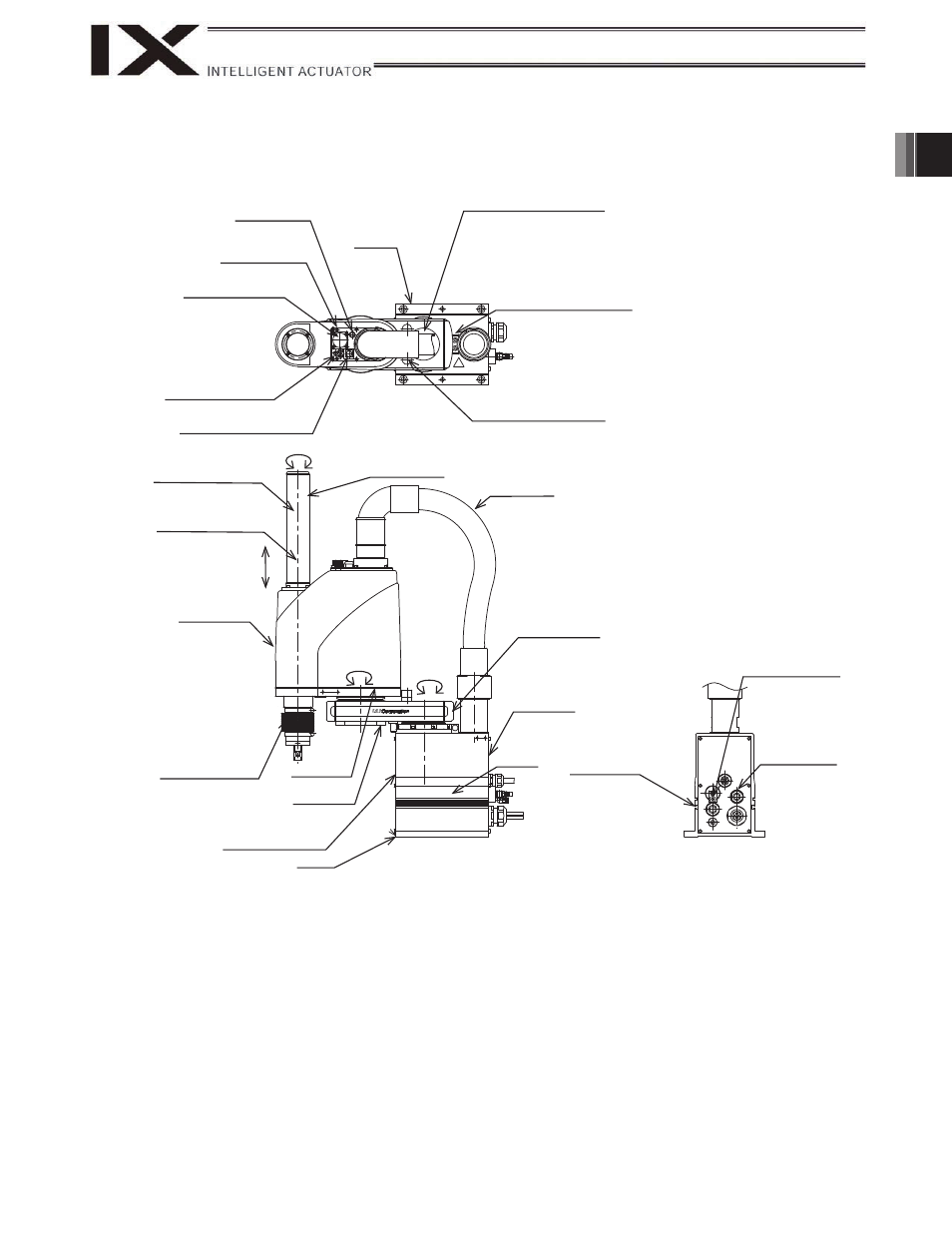
1. Name of Each Part
X-NNW2515H/3515H
3
ALM (indicator)
Reference
surface
Top cover (arm 1)
Mechanical stopper for arm 1
Mechanical stopper for arm 2
BK SW
(Brake- release switch)
User connector
Mechanical stopper for
axis 3 (vertical axis)
Ball screw spline shaft
Axis 3
(vertical axis)
Cover (arm 2)
Mechanical stopper for
axis 3 (vertical axis)
Axis 2
Axis 1
Axis 4
(R-axis)
Wiring duct
End cover (arm 1)
Arm 2
Arm 1
Front panel (base)
Reference surface
Base
Rear panel
(base)
T-slot for peripheral
installation (M3, M4)
Purge air inlet: Outer
diameter
6
(Inner diameter
8)
Applicable tube: Outer
diameter
12
(Inner diameter
8)
4 user piping
(black, red, white; 3
locations)
Duct cover
Spacer for user part
installation
This manual is related to the following products: