21 2. external dimensions – IAI America IX-NNW3515H User Manual
Page 27
21
2. External Dimensions
120
2
1
0
6
5
1
6
0
2
4
7
0
5
2
1
2
125
249.5
5.
6
0
1
0
5
1
T
S
5.
2
0
1
2
6
2
2
6
1
7
125
16
30
8
)
0
7
1(
)
0
0
7(
50
0
4
1
0
6
1
155
185
55
130
0
0
1
(424.5)
92.5
8H10
15
0
3
35
8
0
1
16h7 (
0
-0.018
)
5
1
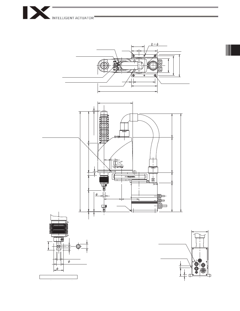
IX-NNC2515H (Arm Length 250, Clean Room Specification)
ALM (indicator)
4 quick air-tube joint
(black, red, white; 3 locations)
User connector
(D-sub 15-pin connector)
BK SW (Brake-release switch)
Arm 2 stopper
Reference
surface
Arm 1 stopper
4-
9
16, counterbore depth 0.5
4 (
M
echa
ni
cal
e
nd)
4
(Me
ch
an
ica
l en
d
)
Tapped hole for peripheral
installation (4-MA, depth 12)
Reference
surface
T-slot for peripheral
installation (M3, M4)
Applicable tube: Outer
diameter
12
(Inner diameter
8)
11 (inner diameter)
Detailed view of arm end
Same on opposite surface
This manual is related to the following products: