29 4. w iring diagram – IAI America IX-NNW3515H User Manual
Page 35
29
4. W
iring Diagram
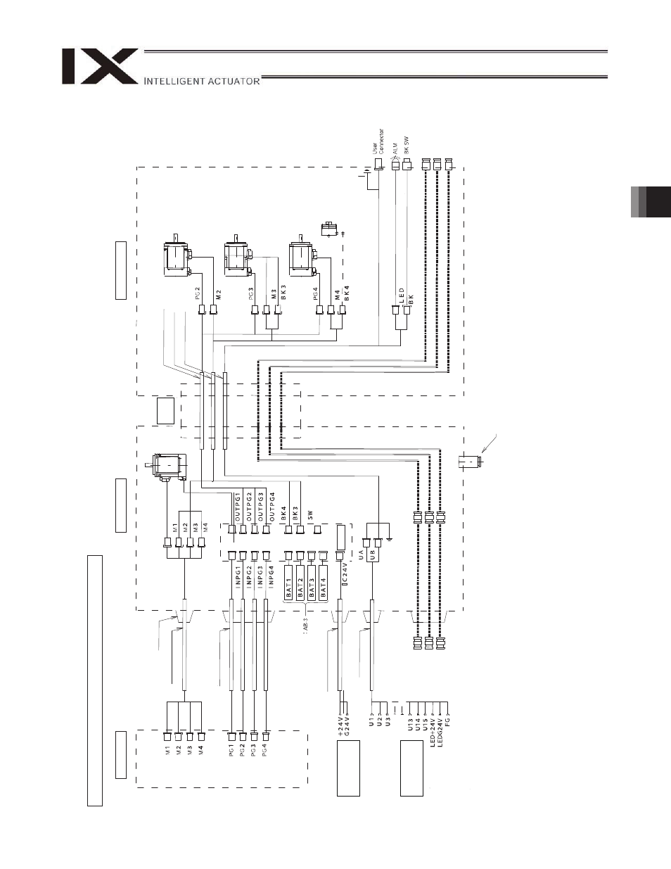
Wiring/Piping Diagram (Arm Length: 250/350)
Notes
(1)
The actual la
y
out
of board conn
ectors varies from t
h
is draw
ing.
(2)
Since the brake
po
w
e
r circuit is provided on the p
rimary
side (high-voltage side)
, a dedicated 24 V po
w
e
r suppl
y
is req
uire
d for this circuit.
The 24 V po
wer
supply
f
or I/
O circuits used on the
secondary
side (low
-voltage side) cannot be share
d.
(3)
To operate the al
arm LED, the
user must provide
a circuit that uses the
controller I/
O output signal.
IX-NNC2515H/3515H
Boar
d
Controller
Inside
base
F
lex
ibl
e
cable
Inside arm 2
Brake po
w
e
r
terminals
User w
iring
terminals
C
abl
e
fi
x
cap (
C
apc
on)
M
cable (
o
utside
r
obo
t)
S
e
rv
o
m
o
to
r
fo
r
a
x
is 1
(a
rm
1
)
PG ca
ble (
inside
r
o
bo
t)
M
cable (
insid
e
r
o
b
o
t)
U cable (
insid
e
r
o
b
o
t)
S
e
rv
o
m
o
to
r
fo
r
a
x
is 2
(a
rm
2
)
S
e
rvo
m
o
to
r w
it
h
br
ake
for
ax
is
3
(Z-axis)
S
e
rv
o
m
o
to
r
fo
r
ax
is 4 (R-axis)
Electr
om
ag
netic
br
ake
for
ax
is
4
FG (
to D-
sub
ho
using
)
D-
su
b
co
n
n
e
ctor
for
u
s
e
r w
ir
ing
(
1
5-
pi
n
, s
o
ck
e
t)
Al
ar
m L
E
D
Br
a
k
e-
release sw
it
ch
fo
r
ax
es 3/
4 (Z/
R
-ax
es)
FG (
T
o
bas
e)
PG ca
ble (
o
u
tside r
o
bo
t)
BK p
o
w
e
r cable (
o
u
tside r
o
b
o
t)
U cable (
o
utside
r
o
b
o
t)
Dedicate
d b
a
tt
er
ies
fo
r IX
Air joint, bl
ack (
4)
Air jo
in
t, re
d (
4)
Air joint, w
h
ite (
4)
Air joint, bl
ack (
4)
Air jo
in
t, re
d (
4)
Air joint, w
h
ite (
4)
Quick suctio
n join
t
(t
ube di
a
m
et
er
12)