28 4. w iring diagram – IAI America IX-NNW3515H User Manual
Page 34
28
4. W
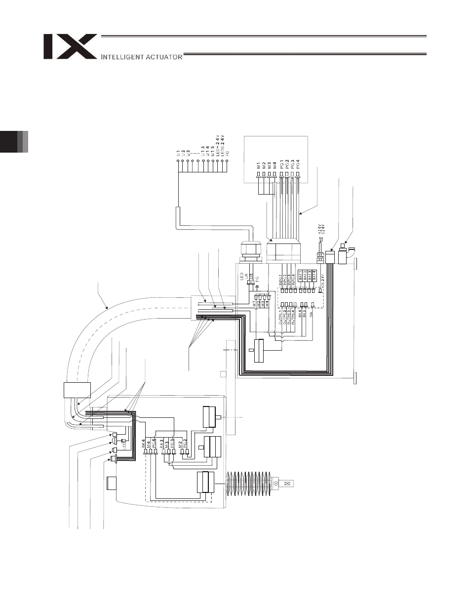
iring Diagram
U c
a
b
le (
ins
id
e r
o
bo
t)
PG
cable
(in
s
ide
ro
bot)
M cabl
e (in
side
rob
o
t)
U c
a
b
le (
ins
id
e r
o
bo
t)
Flex
ible
cable
M cabl
e (in
side
rob
o
t)
PG cable
(inside
robo
t)
U cable
(outside
robo
t)
User w
iring
terminal
s
Controller
M cabl
e
(outside
robo
t)
PG
cable
(ou
tsi
de r
obot)
3-axis moto
r
3-
ax
is e
nco
de
r
2-
ax
is e
nco
de
r
2-axis moto
r
Air tube
s
1
-a
xi
s
enc
od
e
r
1-ax
is moto
r
Air join
t
Black (
4), Red
(
4), Wh
ite
(
4)
,
Air tube
s
Air join
t
Black (
4), Red
(
4), Wh
ite
(
4)
Br
ake p
o
w
e
r
supply
terminal
3-axis brake
4-axis moto
r
4-
ax
is e
nco
de
r
4-axis brake
Air
supply
port
for a
ir purge
Boar
d
Wa
terproo
f con
nector,
15 pi
n
Alarm LED
Brake-
relea
se
sw
itch fo
r ax
es
3/4
(Z/R-ax
es
)
This manual is related to the following products: