26 4. w iring diagram – IAI America IX-NNW3515H User Manual
Page 32
26
4. W
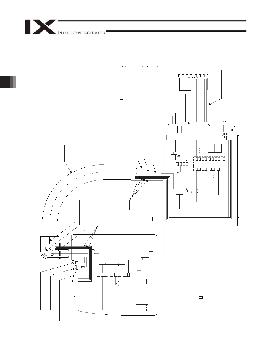
iring Diagram
D
-sub con
nect
or
f
or
us
er
w
iri
ng
(1
5-
oin, s
o
cket)
Al
ar
m L
E
D
Br
ake-
re
leas
e sw
itch for
ax
es 3/4
(Z/R
-ax
es)
Air joint
Black (
4)
, R
ed
4)
, W
h
it
e
(
4)
PG ca
ble (
inside
r
o
bo
t)
M
cable (
insid
e
r
o
b
o
t)
U cable (
insid
e
r
o
b
o
t)
Flex
ible cabl
e
U cable (
insid
e
r
o
b
o
t)
M
cable (
insid
e
r
o
b
o
t)
PG ca
ble (
inside
r
obo
t)
Ai
r tubes
U cable (
o
utside
r
o
b
o
t)
User
w
ir
ing
ter
minals
Co
n
tro
lle
r
M
cable (
o
utside
r
obo
t)
PG ca
ble (
o
u
tside r
o
bo
t)
Br
ake p
o
w
e
r ter
minals
Boar
d
Air joint
Black (
4)
, R
ed (
4)
, W
h
it
e
(
4)
LED
BK4
M4
PG4
BK3
M3
PG3
M2
PG2
LED
UA
U
B
FG
M1
M2
M3
M4
OUT
P
G1
OUT
P
G2
OUT
P
G3
OUT
P
G4
INPG
1
INPG
2
INPG
3
INPG
4
BK
4
BK
3
SW
BAT
1
BAT
2
BAT
3
BAT
4
24 V
DC
+24
V
G
24V
M1
M2
M3
M4
PG1
PG2
PG3
PG4
FG
LED G2
4V
LED
+
24V
U
15
U
14
U1
3
U3
U2
U1
4-
ax
is
en
c
oder
4-
ax
is
m
otor
4-
ax
is
br
ak
e
3-
ax
is
br
ak
e
3-
ax
is
m
otor
3-
ax
is
en
c
oder
2-
ax
is
en
c
oder
2-
ax
is
m
otor
Ai
r tubes
1-
ax
is
en
c
oder
1-
ax
is
m
otor