Ransburg, Appendix m: trigger log, Rcs-2 user manual - appendix – Ransburg RCS 2 Ratio Control System User Manual
Page 76
A new feature has been added to the RCS-2
software package that allows the user to monitor
trigger on and off times, the volume sprayed in
during each trigger on time, and the status of four
discrete (digital) inputs to the RCS-2.
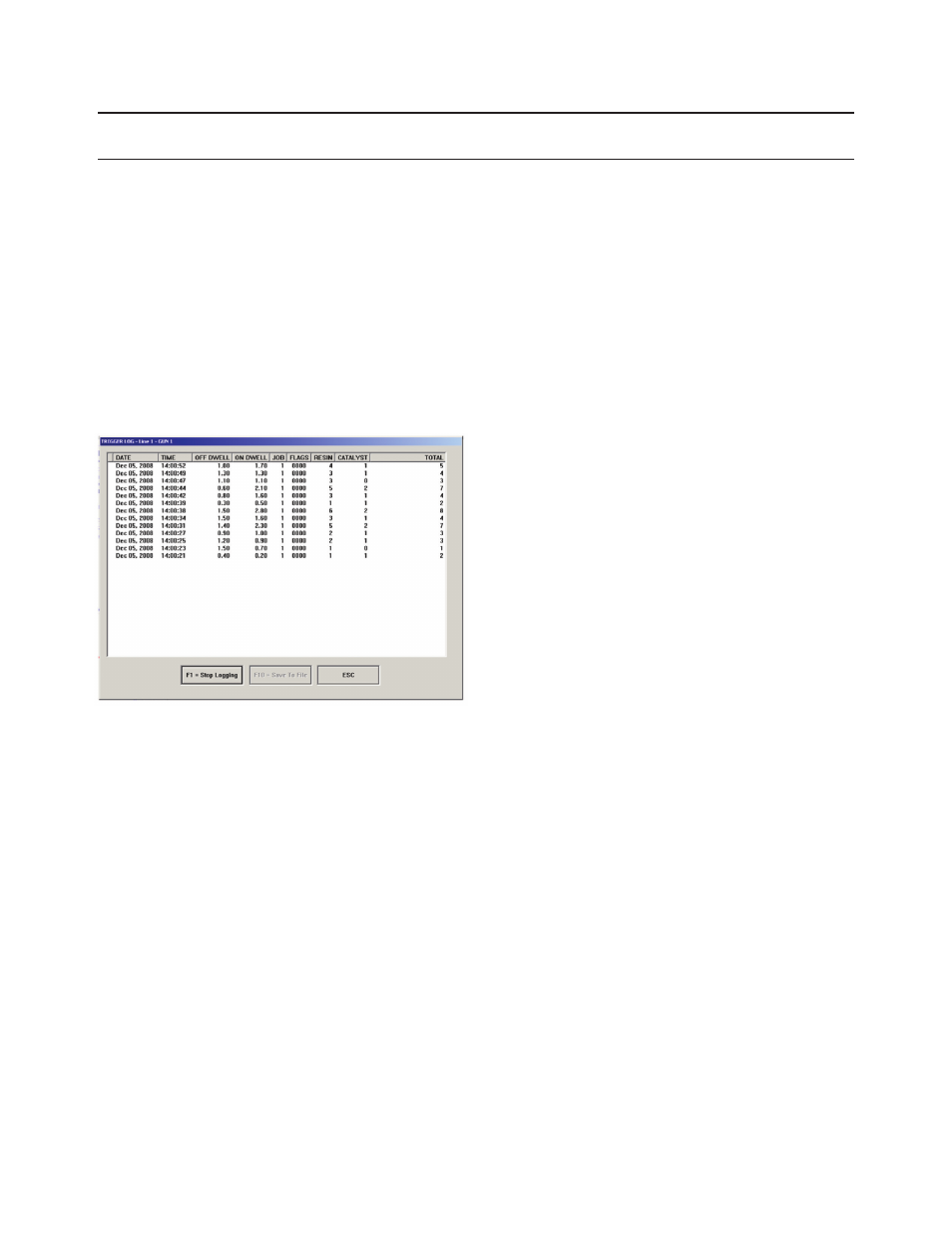
The option is accessed by selecting Function F10
(Trigger Log) from the main screen of the User-In-
terface Software. When you open the Trigger Log
display, a screen similar to this will be displayed
(although there will be no data present).
APPENDIX M: TRIGGER LOG
There will be a START LOGGING function button
displayed that will start logging trigger data as it
occurs. (This button changes to a Stop Logging
button when logging begins.) New data will be
entered on the top line and the older data pushed
down as new data arrives. This data is live, as it
occurs. Note that the very first trigger time (On
Dwell) that occurs after the Start Logging button
is pushed will not be displayed. This is because
the software does not start timing until the first
on to off transition occurs as the Off Dwell time is
always captured first.
Scrolling down to examine data that has scrolled
off of the bottom of the screen is a problem while
data is being captured because every time a new
trigger event occurs, the scroll bar will return to
the top, newest, entry. (This is controlled exter-
nally by the Windows operating system.) Once
the logging is stopped with the STOP LOGGING
function button, the user may easily scroll down
to look at the older events. There is also a SAVE
to FILE function button to create a CSV file of the
logged events using Excel, or any other spread-
sheet program capable of displaying CSV files.
The first column of data is the date that the trigger
occurred (obtained from the real time clock in the
PC running the User-Interface Software.)
The second column of data is the time that the
trigger occurred (obtained from the real time clock
in the PC running the User-Interface Software.)
The third column shows the amount of time (in
seconds) that the trigger signal(s) remained in
the off state. (Trigger Off Condition (Off Dwell) =
Channel A Triggers 1 through 4 must all be off.)
The fourth column shows the amount of time (in
seconds) that the trigger(s) were energized (on).
(Trigger On Condition (On Dwell) = Any time
Channel A receives an trigger input signal. This
can be any of the 4 trigger inputs for channel A.)
The Off Dwell Time is the time from previous
event’s trigger off to the new event’s trigger on,
the On Dwell Time is the time from this event’s
trigger on to this event’s trigger off.
The fifth column indicates what job number was
running in the RCS-2 during this trigger event.
The sixth column shows the status of four binary
flags (digital inputs) at the start of this trigger
event. The four trigger inputs for channel B are
not required for dual component guns and so are
monitored and displayed on the Trigger Log screen
to allow users to use them as flags. (Flags are
RCS-2 User Manual - Appendix
73
LN-9407-00.2
Ransburg