Ransburg, Rcs-2 user manual - installation, Table 3 - system i/o connections – Ransburg RCS 2 Ratio Control System User Manual
Page 30
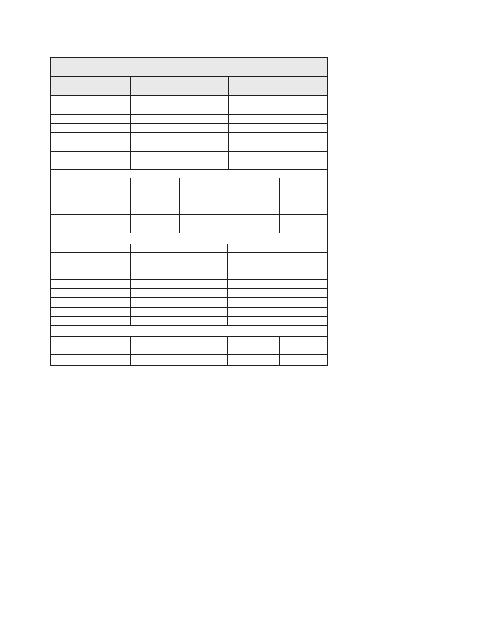
* Reference Drawing Number A10479
** Refer to "Appendix F" for Termination Board Drawing.
Strobe, Gun 1
Strobe, Gun 2
Strobe, Gun 3
Strobe, Gun 4
Strobe, Gun 5
Strobe, Gun 6
Strobe, Gun 7
Strobe, Gun 8
System Signals
CN4012-1
CN4012-3
CN4012-5
CN4012-7
CN4012-2
CN4012-4
CN4012-6
CN4012-8
Terminal
Label
S
S
S
S
S
S
S
S
Channel
Input
Input
Input
Input
Input
Input
Input
Input
Input or
Output
4021
4031
4041
4051
4023
4033
4043
4053
System
Wire No. *
System Fault (Hi)
System Fault (Low)
System Pulse (Hi)
System Pulse (Low)
System User Link (Hi)
System User Link (Low)
Job Number 1
Job Number 2
Job Number 4
Job Number 8
Job Number 10
Job Number 20
Job Number 40
Job Number 80
Job Number 100
Spare System Input
Spare System Input
Spare System Input
CN4012-13
CN4012-14
CN4012-15
CN4012-16
CN4012-17
CN4012-18
CN4012-25
CN4012-27
CN4012-29
CN4012-31
CN4012-33
CN4012-35
CN4012-26
CN4012-28
CN4012-30
CN4012-32
CN4012-34
CN4012-36
S
S
S
S
S
S
S
S
S
S
S
S
S
S
S
S
S
S
Output
Output
Output
Output
Output
Output
Input
Input
Input
Input
Input
Input
Input
Input
Input
Input
Input
Input
4081
4083
4091
4093
4101
4103
4141
4151
4161
4171
4181
4191
4143
4153
4163
4173
4183
4193
TABLE 3 - SYSTEM I/O CONNECTIONS
RCS-2 User Manual - Installation
27
LN-9407-00.2
Ransburg