Ransburg, System inputs & outputs – Ransburg RCS 2 Ratio Control System User Manual
Page 26
System Inputs
Gun Strobe
Type of Input: Gun
Type of Signal: Pulsed
This input signal is used in coordination with the
Job Number inputs (see below). When this input
is taken from the non-energized state to the en-
ergized state for any gun, the Job Number that
is appearing at the Job Number inputs is loaded
into the job queue. If the gun is in the halted,
ready, or faulted state, the new job becomes
active immediately. If the gun is in a run state,
the new job number is held in the queue until the
next time the gun is halted (or faults). Note that
the job queue is only one in length. If another job
is loaded on top of one already in the queue, the
new one overwrites the older one in the queue.
Job Number (1, 2, 4, 8, 10, 20, 40, 80, 100)
Type of Input: System
Type of Signal: Maintained
These inputs are simple BCD (binary coded dec-
imal) inputs that represent the job number that
an external controller energizes to load new job
numbers into the RCS-2 guns. Note that these
inputs are common to all guns and they are ig-
nored until one or more of the Gun Strobe inputs
is energized. Allowable job number range from
1 to 199.
System Outputs
System Fault
Type of Output: System
Type of Signal: Maintained
This output is normally connected to the horn in
the top of the control console. It can be energized
anytime there is a system fault. (It can be enabled
and disabled on the CONFIG SYSTEM screen.)
Some examples of system faults are problems
with the disk drive, hard drive, or CDROM of the
user-interface PC. Also, certain problems with
the interface board or RIO board (if used) may
cause a system fault.
This output can also be programmed to energize
when any of the guns fault. This is done on the
CONFIG GUN screens. Each gun can be con-
figured to cause the horn to sound when it faults
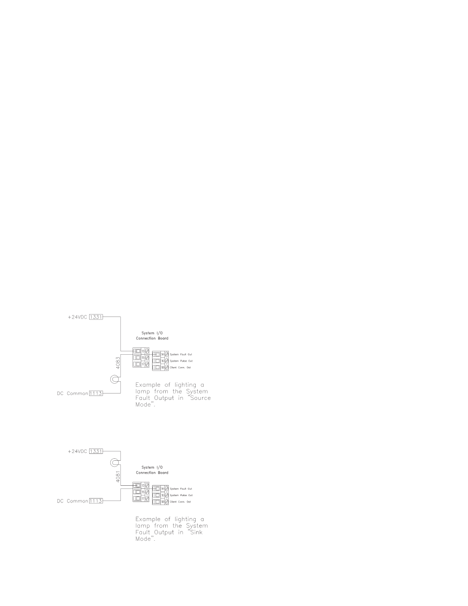
Figure 12: System I-O Sourcing-Sinking
SYSTEM INPUTS &
OUTPUTS
All discrete system inputs and outputs can be
configured to either sink or source current. All
system inputs connect to the system via the inter-
face board. Refer to " Appendix D" to configure
the jumpers on the interface board for the discrete
system inputs.
To source (current or voltage) from the system
outputs, simply connect the positive terminal of the
desired output to the positive terminal of a power
supply (10 VDC to 40 VDC) and the negative
terminal of the desired output to the positive input
of the device. The negative input to the device
must be grounded to the aforementioned power
supply. To sink current on the interface board,
simply connect the negative output terminal of
the desired output to ground, the positive output
terminal to the negative input to the device, and
the positive input to the device to the positive
terminal of the appropriate power supply.
RCS-2 User Manual - Installation
23
LN-9407-00.2
Ransburg