Installation, English, Cable gland to remove – Burkert Type 8175 User Manual
Page 88: Power supply
20
8175
ENGLISH
INSTALLATION
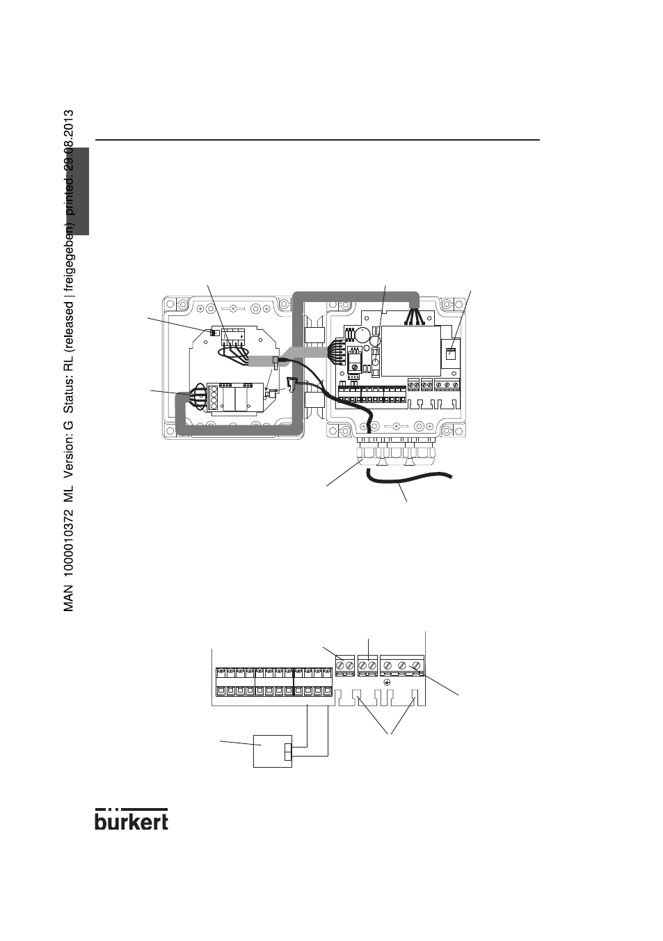
3.4.5 8175 Wall Mounted Version 115/230 VAC
Connection of the 8170 sensor
-
Open the cover after having unfasten the 4 screws on the front display.
-
Replace one of the housing cable glands through the cable gland inserted on the sensor
cable.
-
Connect the coax and PT1000 cables as shown in the diagram below.
8175 wall mounted version 115/230 VAC with or without relays; Wiring
Remove the cover via the screws on the front display and pull the cable through the cable
gland then wire according to the pin assignment diagram below.
To connect the transmitter to a PLC, use terminals 10 and 12 and set SW2 to position A
(see figure above).
Terminals 13 to 16 must only be connected if the transmitter is a version with relays.
-
+
Cable gland to remove
SW 2,
Position A
Wires: Pink - Blue - Red - Black
250-mAT-fuse
115/230 VAC Po-
wer Supply switch
Cables with diameters between 4 and 8 mm.
1
2
3
4
5
6
7
8
9 10 11 12
13 14
15 16
L
N
4-20 mA
+
-
I
L+ L-
R1 R1
R2 R2
115/230 VAC
Power Supply
Relay 1
Relay 2
For security reasons, secure the
cables onto the board using the
cable clips provided.
PLC, valve or positioner
Wires:
Brown
White
Yellow
Green