Installation, English – Burkert Type 8175 User Manual
Page 81
13
8175
ENGLISH
INSTALLATION
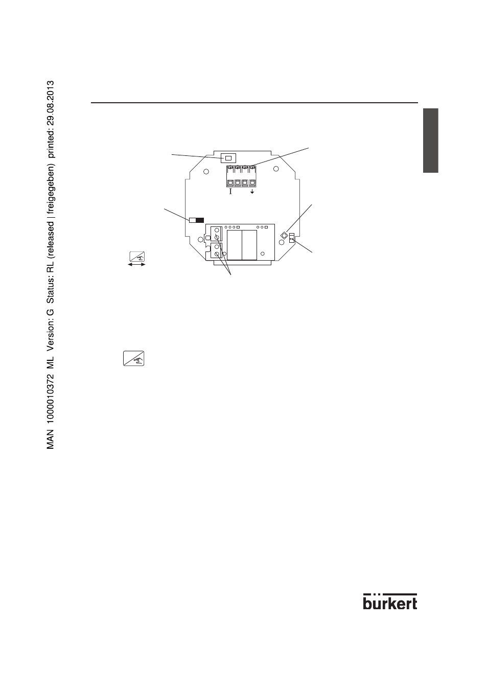
3.3 18-32 VDC ELECTRONIC CARD IDENTIFICATION
-
The Coax cable and PT1000 connections must be connected in all cases to ensure the
device functions correctly.
-
The
ENTER
key can be locked to avoid accidental or unauthorised access by placing
SW1 in the left position in the diagram above.
3.4 GENERAL ELECTRICAL CONNECTION
-
Use cables with a temperature limit of 80°C minimum.
-
For normal operating conditions the measuring signal can be transmitted by a simple
cable of 0.75 mm
2
cross section.
-
The line must not be installed in combination with carrying lines with a higher voltage or
frequency. If a combined installation cannot be avoided, a minimum space of 30 cm
(1 ft) or shielded cables should be adopted.
-
When using shielded cables observe faultless grounding of the shield.
-
For EMC purposes,the earth must be connected via the earth lug on the side of the
enclosure (see fig. 3.2). This point must be connected locally to a good earth.
-
The cable diameters for the cable gland versions must respect the following:
Compact: between 6-12mm and 6 mm with a multiway seal
Wall mounted: between 4-8mm (not used cable glands must be blanked off).
-
In case of doubt, always use shielded cables.
-
The 18-32 VDC power supply must be filtered and regulated - section 6.1.
SW 2 - Sourcing or
sinking configuration.
Terminal connections -
Connection of power supply
of 18-32VDC and 4-20mA
output.
SW 1 - Locking of the
‘Enter‘ key to avoid
accidental or unau-
thorised access to the
calibration and test
menus.
Sensor Coax cable
connection.
PT1000 connection.
Relay connections - Connection of relays 1 & 2 (optional).
-
+
4
3
2
1
ENTER
Locked
Unlocked