Installation, English – Burkert Type 8175 User Manual
Page 85
17
8175
ENGLISH
INSTALLATION
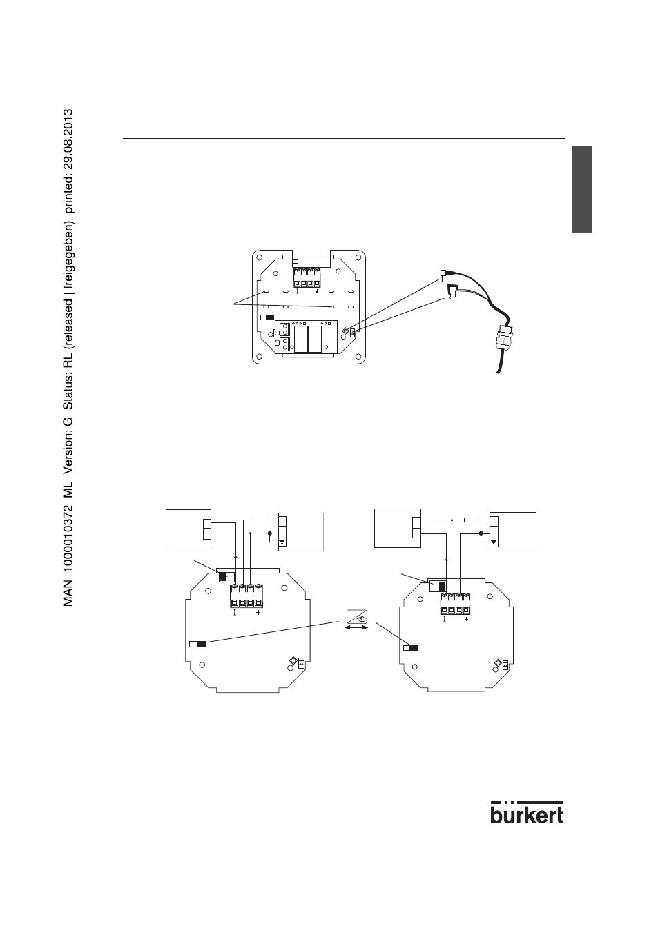
8175 panel version 18-32VDC, wiring
Open the cabinet/cupboard and wire according to the pin assignment diagrams below.
The electronics within the 8175 allows a sourcing or sinking PLC to be connected. Position
A (Fig 3.11) provides a sourcing configuration and Position B (Fig 3.12) a sinking configu-
ration.
Fig. 3.11 Pin assignment, Position A
Fig. 3.12 Pin assignment, Position B
3.4.3 8175 panel version 18-32VDC
Connection of the 8170 sensor
-
Pass the cable through the wall / panel and use the cable gland to secure the cable.
-
Connect the coax and PT1000 temperature cables as shown in the diagram below.
-
Secure all the cables onto the protection plate as indicated via the 2 plastic ties
provided.
PT1000
Coax
Secure the cables
onto the protection
plate using the plastic
ties
Fig. 3.10 Panel cable
connections
4-20 mA
+
-
18-32 VDC
+
-
250 mA
I
-
+
4
3
2
1
(*)
4-20 mA
+
-
18-32 VDC
250 mA
I
-
+
4
3
2
1
+
-
(*)
PLC/control
valve or
positioner
SW 2,
Position A
SW 2,
Position B
PLC/control
valve or
positioner
ENTER
Locked
Unlocked
SW1
-
+
4
3
2
1
(*) If direct earthing is impossible, connect a 100 nF/50 V-condensator between the negative terminal of the power
supply and the earth.