Installation, English – Burkert Type 8175 User Manual
Page 86
18
8175
ENGLISH
INSTALLATION
-
+
4
3
2
1
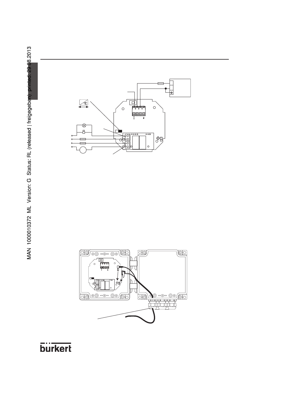
8175 panel version, relay connection
The relay version is connected as follows :
Fig. 3.13 Pin assignment for relays
-
The device can be easily connected to a PLC independently of the respective version.
-
The ‘Enter‘ key can be locked by placing the SW 1 swich into the left position to avoid
accidental or unauthorized access.
3.4.4 8175 Wall Mounted Version 18-32VDC
Connection of the 8170 sensor
-
Open the cover after having unfasten the 4 screws on the front display.
-
Replace one of the housing cable glands through the cable gland inserted on the sensor
cable.
-
Connect the coax and PT1000 cables as shown in the diagram below.
Cable gland to remove
Fig. 3.14 Wall cable connections
4-20 mA
18-32 VDC
250 mA
3A
m
24VDC
115/230 VAC
3A
-
+
4
3
2
1
REL1
REL2
+
-
(*)
SW 1
ENTER
Locked
Unlocked
OR
(*) If direct earthing is
impossible, connect a
100 nF/50 V-condensa-
tor between the negative
terminal of the power
supply and the earth.