Installation, English – Burkert Type 8175 User Manual
Page 87
19
8175
ENGLISH
INSTALLATION
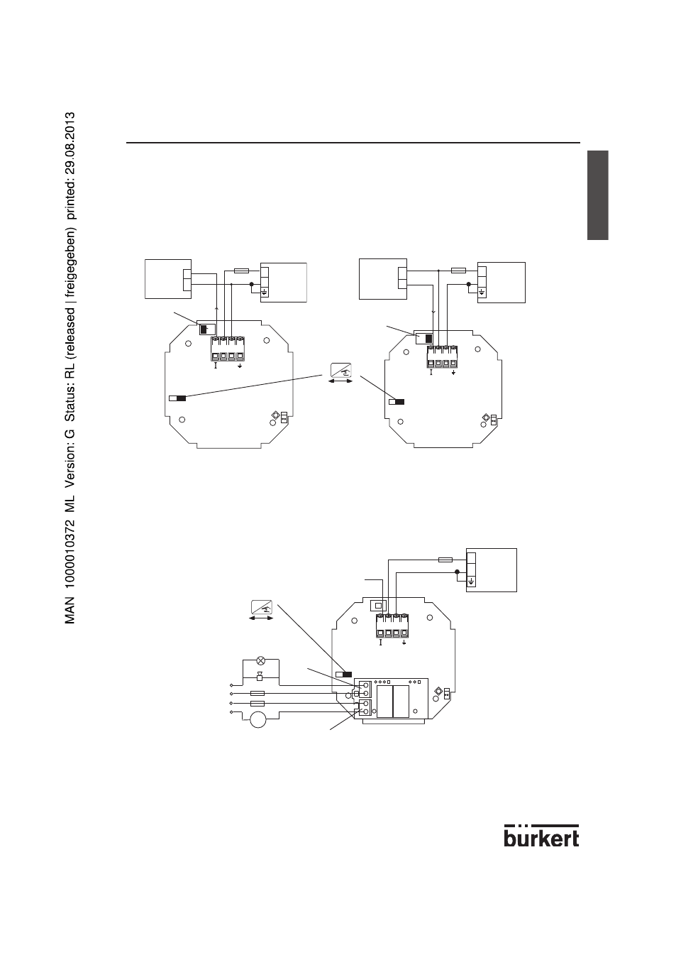
8175 wall mounted version, 18-32 VDC; WIRING
Remove the cover via the screws on the front display and pull the cable through the cable
gland and wire according to one of the pin assignment diagrams below.
The electronics within the 8175 allows a sourcing or sinking PLC to be connected. Position
A (Fig 3.15) provides a sourcing configuration and Position B (Fig 3.16) a sinking configu-
ration.
Fig. 3.15 Pin assignment, Position A
Fig. 3.16 Pin assignment, Position B
8175 wall mounted version, relay connection
The electrical wiring of this model is possible via the use of 2 of the cable glands. Remove
the cover via the screws on the front display and pull the cables through the cable gland
and wire according to pin assignment diagram below (Fig. 3.17).
-
The device can be easily connected to a PLC independently of the respective version.
-
The ‘Enter‘ key can be locked by placing the SW 1 swich into the left position to avoid
accidental or unauthoridsed access.
Fig. 3.17 Pin assignment for relays
4-20 mA
+
-
18-32 VDC
+
-
250 mA
I
-
+
4
3
2
1
(*)
4-20 mA
+
-
18-32 VDC
250 mA
I
-
+
4
3
2
1
+
-
(*)
4-20 mA
18-32 VDC
250 mA
3A
m
24VDC
115/230 VAC
3A
-
+
4
3
2
1
REL1
REL2
+
-
(*)
PLC/control
valve or
positioner
SW 2,
Position A
SW 2,
Position B
PLC/control
valve or
positioner
ENTER
Locked
Unlocked
SW1
SW 1
ENTER
Locked
Unlocked
OR
(*) If direct earthing is
impossible, connect a
100 nF/50 V-condensa-
tor between the negative
terminal of the power
supply and the earth.