Installation, English – Burkert Type 8175 User Manual
Page 82
14
8175
ENGLISH
INSTALLATION
-
Do not open and wire the transmitter with the power supply connected.
-
It is obligatory to put security devices close to the transmitter, on:
Power supply : 18-32VDC - 250mA fuse and interrupter
115/230VAC - 5A fuse and a bipolar interrupter
Relay :
3A fuse max. and a bipolar interrupter
(depending
on
the
application).
-
Do not apply both a dangerous voltage and a very low safety voltage to
the
relays.
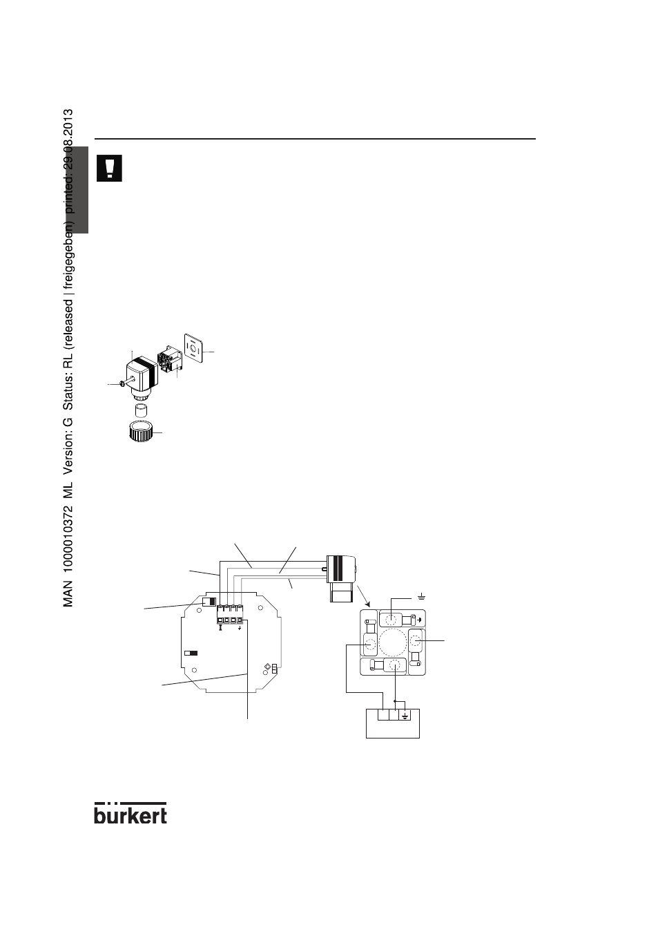
3.4.1 8175 Compact version with an EN 175301-803 connector
Wiring
-
+
4
3
2
1
1
3
2
+ -
EN 175301-803
(*)
1. To open the connector remove screw 1 (Fig. 3.3).
2. Remove the internal part 3 from the external casing 2.
3. Connect the transmitter according to the pin
assignment in Fig. 3.3
4. When re-assembling, the internal part 3 can be rotated
in 90° steps to a desired position before inserting back
into the casing 2.
5. Tighten the cable gland 5. Then place gasket 4
between the EN 175301-803 connector and the fixed
connector of the transmitter and plug the
EN 175301-803 connector onto the transmitter.
6. Tighten screw 1.
Fig. 3.3 Plug assembly
I (4-20 mA output)
Orange
Red
Black
Brown
Green/Yellow
To the earth lug of the housing
Power supply
+ (L+; 18-
32 VDC)
- (L-)
To position SW2,
see 3.4.2, compact
version with cable
gland
(*) If direct earthing is
impossible, connect a
100 nF/50 V-condensa-
tor between the negative
terminal of the power
supply and the earth.
4
3
1
5
2