ABUS AZ4299 Terxon SX Base Kit with sounder Installation User Manual
Page 91
15
UK
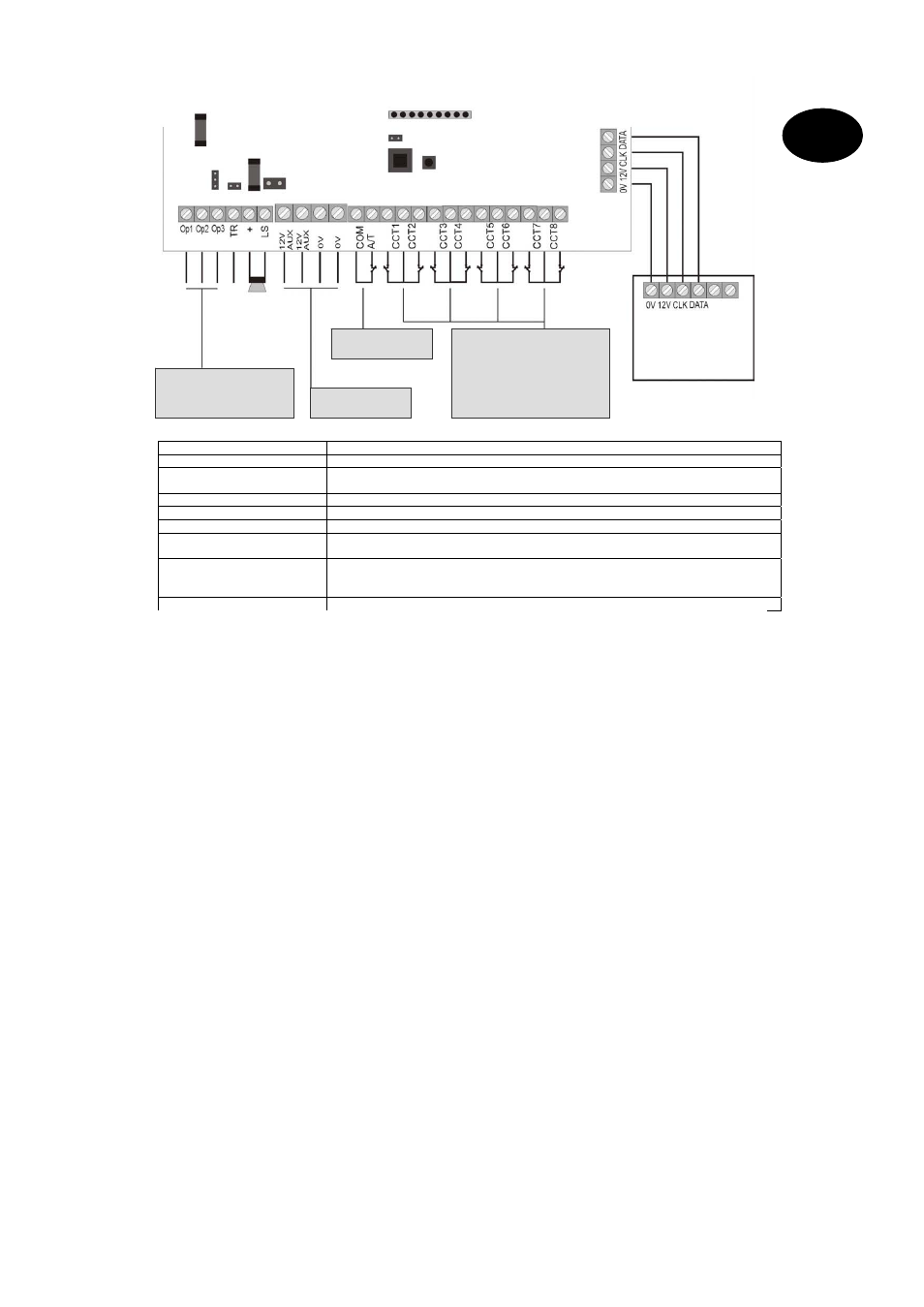
Connection
Meaning
AC mains supply unit (AC IN)
Contact for 230V main supply unit
Kick Start jumper (KS)
Connect the two contacts of this jumper to start the alarm centre without a 230V mains
power supply.
Battery contact (+ -)
Connecting plug from standby power supply
COMMS interface
Contact for additional transistor outputs
Reset jumper (NVM RST)
Connect the two contacts of this jumper to reset the alarm centre.
Fuses (BAT F-2A / 12VAUX F-
1A)
Always use fuses of the same type. To avoid problems, make sure there is always a good
contact between the fuse holder and the fuse.
Siren sabotage input (TR)
For sirens with their own power supply, connect this input direct to the tamper output of the
siren. Otherwise, connect the tamper contact of the siren to the loop between the TR input
and 0V. If no siren is used, connect the TR input direct to the 0V output.
Optional loudspeaker (LS)
Connect a 16 Ohm loudspeaker for internal alerts.
Programmable transistor outputs
(OP). Max. power consumption of all
transistor outputs 0.5A.
Siren t
amper
it Opt
ional
loudspea
ker
it
12V power supply for
external components (e.g.
Tamper input for external
components (e.g.
Alarm zone 1–8 for NC alarm contacts (e.g.
IR sensor). No NO contacts can be
connected. Make sure the alarm zones are
terminated with the corresponding resistors.
Either two different resistors or no resistor
must be used, depending on programming.
If the zone is used, remove the wire jumper.
Control unit
1A AUX fuse for
power supply
2A BAT fuse for
battery charging
AC
connector of
transformer
Kick
star
Battery
connector
COMMS
interface
NVM
EEPROM
Lid tamper contact